WWW.BALTIMOREAIRCOIL.COM
5
Section Assembly of Two-Piece Cells
1.
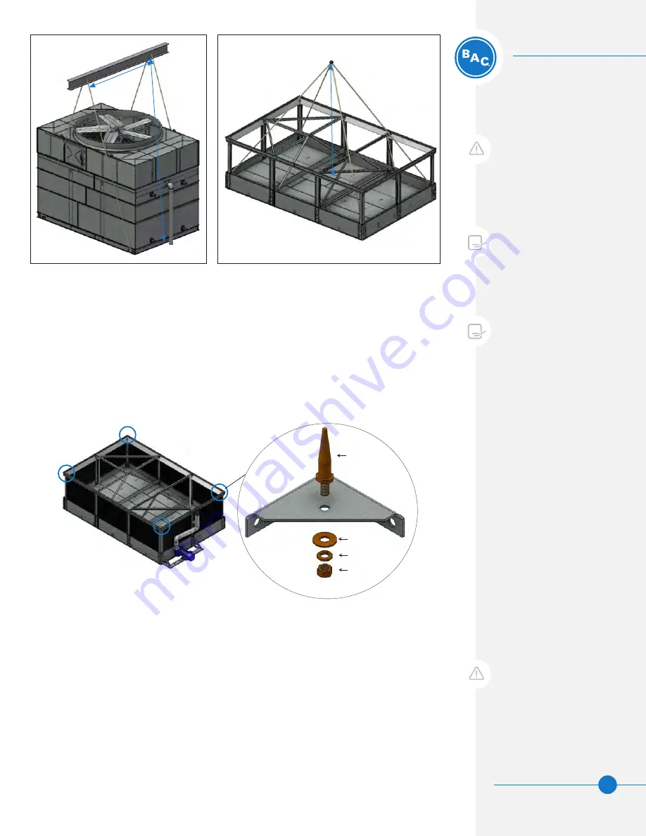
Figures 2 and 3
show the proper rigging of sections for units that ship in two pieces.
2. Remove any motors or accessories shipped in the lower section.
3. For units that ship with rigging alignment pins, install the pins on the cold water basin
in the locations shown in
Figure 4
. Secure the alignment pins using the 1/2” hardware
provided from the factory.
NOTE:
All pump piping must be
restrained to ensure no vertical or
horizontal movement. All piping
and supports are to be furnished
by others. Refer to the submittal
drawing for details on piping
connection sizes, etc.
PF
i
AND PCC
Unit Rigging & Assembly
Unit Rigging & Assembly
Rigging
Section Assembly of
Two-Piece Cells
NOTE:
The IBC Rating is void if the
section assembly is not performed
as described in this manual.
Figure 2.
Upper Section Two-Piece Lift
(Casing and Mechanical)
Figure 3.
Lower Section Two-Piece Lift
H
H
W
WARNING:
Do not lift the
mechanical (top) section attached
to the coil casing section from the
mechanical section lifting ears. Lift
both sections from the coil casing
lifting ears.
CAUTION:
Any motors or
accessories shipped in the cold
water basin must be removed prior
to installing the upper (mechanical
and coil casing) section.
Figure 4.
Alignment Pin Locations
1/2” Flatwasher
Alignment
Pin
1/2” Lockwasher
1/2” Nut
Detail A
4. Position the lower section on the steel support and bolt in place.
5. Wipe any moisture or dirt from the top perimeter flange of the lower section.
6. Install flat butyl sealer tape (BAC part # 554000) supplied with the unit, on the
mating flanges of the lower section in a continuous line. At each corner, allow 1”
overlap.
7. Lower the hose connection on the pump discharge piping below the elevation of the
lower section before rigging the coil casing section.
8. Lower the upper section (coil casing and mechanical) until it is hovering 2-6” above
the lower section.


