background image

4

A U T O M A T I O N   &   C O N T R O L

G75-DFC

Differential Filtration Controller

INTRODUCTION

General

The Baccara Differential Filtration Controller combines a Controller and a Differential Pressure Sensor (DP).
The Controller has seven wires; four wires for valves, and a molded 3 wire cable with connector for the DP switch. 
The G75-DFC operates up to three G75 4

 latch two-wires solenoids, and has a display screen that shows the actual 

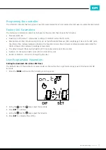
differential pressure (DIF) and the pressure SET point. 
The Flushing Cycle (FC) begins when the DIF reading is greater than or equal to the SET value.

Display:

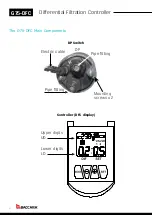
The LCD display shows:
•  The actual differential pressure - DIF
•  The pressure set point - SET
•  The flushing cycles counter - FC
•  While in flushing, a Faucet icon appeases on screen 
•  When the battery needs replacing, a Low Battery icon appears on screen

Technical Data

Controller Set | Supplied with

DFC controller, suitable for DC only, and one analog sensor

Mechanical

•  Operating temperature: -10ºC to 60ºC
•  Outdoor UV protection
•  Front panel cover protection
•  “H” proof pressure: 14 bar (203 PSI)
•  “H” pressure must be ≥ “L” pressure

Electrical

DC units are powered by single 9V alkaline battery.
•  Back-up memory
•  Low battery warning
•  Power saving LCD

Mounting

•  Pressure ports 1/8” BSP/NPT (male)
•  High pressure port is marked by the letter “H” on the housing
•  Connect high pressure before low pressure
•  Disconnect low pressure before high pressure

   Controller:

•  Directly on a 28mm diameter solenoid in horizontal or vertical position with adaptor
•  Wall mounting with four screws
•  Accessories provided | Sensor: 2” (52 mm diameter)

Software

See the “Programming” chapter of this document

Options

Option to change default factory settings

Standard protection class

IP66 | Dust and watertight

Solenoid

G75-A, GALIT Latch 4

, G75-A3P 1

Summary of Contents for G75-DFC

Page 1: ...G75 DFC A U T O M A T I O N C O N T R O L Tackling climate change together Differential Filtration Controller Installation Operation Maintenance IOM...

Page 2: ...part any part of this document or its content The confidential nature of and or privilege in the file enclosed is not waived or lost as a result of a mistake or error in this file If you received this...

Page 3: ...Waterproof Small Wire Connector LV9000 8 DryConn 22 to 12 AWG Wire Connectors 8 Provided by DryConn 8 BATTERY INSTALLATION 9 Before installing the battery 9 Replacing the battery 9 The User Interface...

Page 4: ...replacing a Low Battery icon appears on screen Technical Data Controller Set Supplied with DFC controller suitable for DC only and one analog sensor Mechanical Operating temperature 10 C to 60 C Outdo...

Page 5: ...vant standards and regulations Electrical wiring should be performed by an authorized electrician only using standardized and approved components and tools Locate the G75 DFC Filtration Controller whe...

Page 6: ...ontroller The G 75 DFC Main Components Electric cable Pipe fitting Mounting screws x 2 Pipe fitting Controller D Upper digits UD Lower digits LD DP Pipe fitting Mounting screws x 2 Controller DFC disp...

Page 7: ...e Connects to the black wire of solenoid number 3 filter valve 3 Black wire of the Differential Pressure switch DP Switch Installation Connect the controller s molded cable with the 3 wire connector t...

Page 8: ...ed connection Do not reuse DryConn 22 to 12 AWG Wire Connectors Provide by DryConn 1 Strip 22 18 wires 1 2 12 7mm And 16 12 wires 3 8 9 5mm 2 Align any frayed strands or conductors 3 Pre twisting unne...

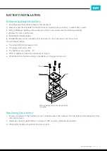
Page 9: ...k the cover and secure the four screws The LCD display shows The actual differential pressure DIF The pressure set point SET The flushing cycles counter FC While in flushing a Faucet icon appeases on...

Page 10: ...the controller is paused such as off season or when controlling the filters is not required In the OFF mode the lower line of the controller LD displays OFF In this mode the controller stops reading t...

Page 11: ...samples shortens The maximal interval time between readings is 60 seconds while the minimal interval time between readings is 5 seconds The delay between filters during flushing Off time between valve...

Page 12: ...the above process for filters number 2 and 3 2 Using the and the keys adjust the minutes If A is selected press SET to complete the setting 3 Press SET to continue 4 Using the and the keys adjust the...

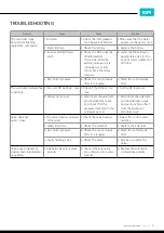
Page 13: ...y 1 Incorrect DP settings Low 1 Check if the DP is set too low 1 Set the DP to 0 5 bar 2 Sensor not zeroed 2 Disconnect the upstream and downstream tubes and check that the pressure indicated in the o...

Page 14: ...yer shall deliver the product to one of Baccara s facilities and collect it from the same facility once repair is completed G75 DFC 22 04 21 Page 15 of 15 Warranty Baccara Geva ACS Ltd Baccara product...

Page 15: ...15 G75 DFC Differential Filtration Controller IOM IOM...

Page 16: ...3 9553 4963 F 61 0 3 9553 4965 Cheltenham Victoria 3192 Australia australia baccara geva com www baccarageva com au Store www baccarastore com au BACCARA Espa a C Marqu s de Monteagudo N 24 Madrid T 3...

Reviews: