background image

Instruction 19-9326

9

Monoxor III

1.  Enter the Setup Mode per Secton 3.4.1. If necessary, repeatedly 

press 

ENTER


untl the Temperature Unts Setup Screen s dsplayed. 

2.  Press the 

 or 


button untl the desred temperature unt 

(°F or °C) s dsplayed.

3.  Press 

ENTER


to move to the next Setup Screen, or 

I/O

 to ext setup.

3.4.3  CO Channel Zero Setup

The CO Channel Setup Screen s labeled “CO”.

1.  Enter the Setup Mode per Secton 3.4.1. If necessary, repeatedly 

press 

ENTER


untl the CO Channel Setup Screen s dsplayed.

2.  Press the 


or 

 button untl the desred parameter s dsplayed. 

- no  

Sensor disabled. 

Note that when the CO sensor s ds

-

abled the CO measurement screen wll dsplay “Err” n

-

stead of the current CO level.

- 2Ero 

Manual Zero

 – Warm-up time is 10 seconds, and the 

analyzer 

does no

t zero the CO sensor to ambent condtons 

durng ths perod. For example, f the atmosphere con

-

tans 25 ppm CO at start up, the analyzer wll mmedately 

dsplay 25 ppm. The zero pont, however, can be manually 

adjusted by performng Steps 1–4 of Secton 5.3.

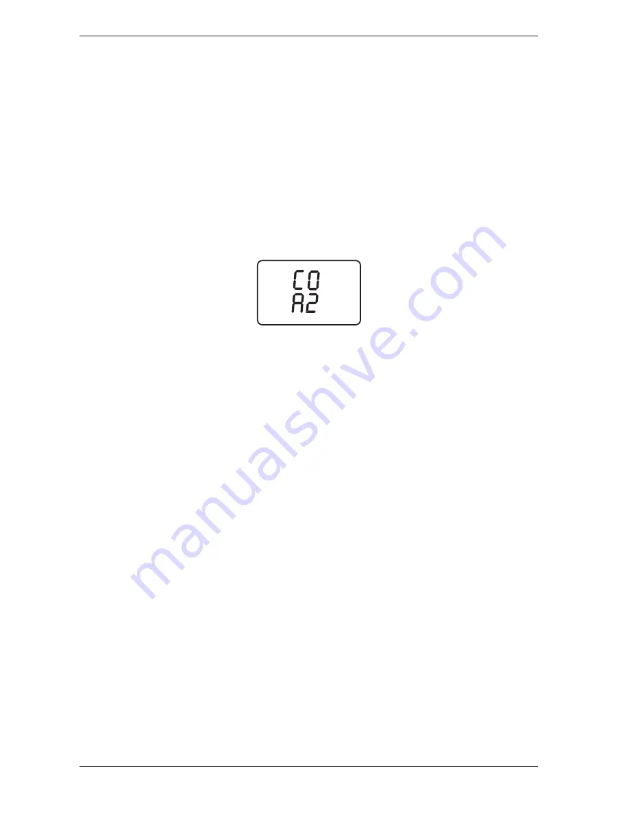
- A2  

Auto Zero

 – Warm-up time is 60 seconds, and the CO sen-

sor s zeroed to the ambent CO level durng ths perod. For 

example, f the atmosphere contans 25 ppm CO at start up, 

the analyzer wll dsplay 0 ppm. 

It’s very important that 

when in this mode the analyzer be turned ON in fresh 

air; otherwise, incorrect CO readings will occur. 

3.  Press 

ENTER


to move to the next Setup Screen, or 

I/O

 to ext setup.

Summary of Contents for 19-8104

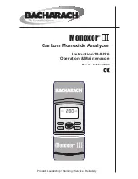
Page 1: ...Monoxor III Carbon Monoxide Analyzer Instruction 19 9326 Operation Maintenance Rev 2 October 2003 Product Leadership Training Service Reliability ...

Page 2: ...he Buyer shall be limited to those provided herein to the exclusion of any and all other remedies includ ing without limita tion incidental or consequen tial damages No agree ment varying or extending the foregoing warranties remedies or this limita tion will be binding upon Bacharach Inc unless in writing signed by a duly authorized officer of Bacharach A Register Your Warranty by Visiting www ba...

Page 3: ... Taking a Gas Sample 13 4 2 Ending a Test 14 4 3 Turning OFF the Analyzer 14 4 4 CO Purge During Turn OFF 14 4 5 CO Sensor Error Screen 15 4 6 Using the Backlight 15 4 7 Using the Probe 15 4 8 Operating Tips 16 4 9 Resetting the Microprocessor 16 4 10 Printing Test Results 17 5 0 CALIBRATION MAINTENANCE 19 5 1 Entering the Calibration Mode and Testing the Display Segments 19 5 2 Ambient Temperatur...

Page 4: ...Monoxor III Instruction 19 9326 ii Notes ...

Page 5: ...here the sample is analyzed for the presence of CO If CO is detected the CO ppm level is displayed on the analyzer s LCD A permanent record of the detected CO level along with the current time and date can be made by using the optional wireless IrDA printer A backlight enables the operator to read the display in dimly lit areas A power saver feature causes the backlight to automatically turn OFF a...

Page 6: ...Instruction 19 9326 Monoxor III Notes ...

Page 7: ...p Time 10 or 60 seconds depending on CO channel zero setup refer to Page 9 Display 4 digit by 2 line 7 segment Liquid Crystal Display Front Panel Controls Six push button switches refer to Section 3 3 Operating Temperature Analyzer 32 104 F 0 40 C Probe 1000 F 538 C max at 5 insertion Humidity 15 to 90 RH non condensing Printer Port IrDA or HP protocol Weight 16 oz with batteries Size 7 5 H x 3 1 ...

Page 8: ...Instruction 19 9326 Monoxor III Notes ...

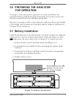
Page 9: ...he analyzer calibrated on 500 ppm CO at the factory 3 1 Battery Installation Install fresh batteries as described below Check the analyzer for sufficient charge prior to each use Replace the batteries if the low battery symbol appears in the lower right corner of the LCD To install batteries 1 Remove battery cover from back of unit see Figure 3 1 2 If old batteries are installed remove and properl...

Page 10: ...e probe if the analyzer is going to be used for flue gas CO mea surements or if gas measurements need to be taken from a cramped or confined area To install the probe simply slide its hose over the GAS inlet of the ana lyzer see Figure 3 2 Figure 3 2 Probe Connection ...

Page 11: ...R Starts a test pump ON Sets up the analyzer to be placed into its Calibration Mode when held down with the analyzer OFF Used in conjunc tion with the I O button Stores the displayed value and automatically steps to the next screen when pressed during calibration or setup Displays the CO screen when held down for 2 seconds while in the Calibration Mode Aborts turn off and keeps the analyzer turned...

Page 12: ...ntering Setup 1 With the analyzer turned OFF press and hold down the HOLD button 2 Press and release the I O button 3 Release the HOLD button 4 The analyzer is now in its Setup Mode Refer to Sections 3 4 2 thru 3 4 7 for information on how to set the analyzer s various parameters 3 4 2 Temperature Units Setup The Temperature Units Setup Screen is labeled Unit Note The analyzer uses an internal tem...

Page 13: ...r is dis abled the CO measurement screen will display Err in stead of the current CO level 2Ero Manual Zero Warm up time is 10 seconds and the analyzer does not zero the CO sensor to ambient conditions during this period For example if the atmosphere con tains 25 ppm CO at start up the analyzer will immediately display 25 ppm The zero point however can be manually adjusted by performing Steps 1 4 ...

Page 14: ... ENTER to move the selection bars over the minute digits 4 Press the or button until the correct minute value is displayed 5 Press ENTER to move to the next Setup Screen or I O to exit setup 3 4 5 Date Setup There are two Date Setup Screens each labeled DAtE The first screen sets the month while the second screen sets the day 1 Enter the Setup Mode per Section 3 4 1 If necessary repeatedly press E...

Page 15: ...ol The Printer Setup Screen is labeled Prnt The analyzer can be set up to send data to a wireless printer using either HP or IrDA protocol 1 Enter the Setup Mode per Section 3 4 1 If necessary repeatedly press ENTER until the Printer Setup Screen is displayed 2 Press the or button to select the desired protocol 3 Press ENTER to move to the next Setup Screen or I O to exit setup 3 4 8 Exiting the S...

Page 16: ...Instruction 19 9326 12 Monoxor III Notes ...

Page 17: ...d by a screen that counts down the warm up period The warm up period is either 60 seconds Auto Zero Mode or 10 seconds Manual Zero Mode Following warm up the CO screen appears This screen shows the current detected CO level in ppm If the probe is being used insert the probe tip into the area to be sampled Note If a sensor error was detected during warm up the CO Sensor Error Screen will be display...

Page 18: ... however will abort the count down and keep the analyzer ON Note The analyzer will automatically turn itself OFF after 20 minutes of keyboard inactivity unless the detected CO level is above 50 ppm 4 4 CO Purge During Turn OFF If the detected CO level is above 50 ppm when the analyzer is turned OFF the unit will remain ON with its pump running and display PUrG CO The countdown from 5 will not begi...

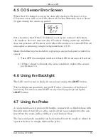
Page 19: ...spent or defective sensor 1 Turn OFF the analyzer and turn it back ON in an area of fresh air 2 If Step 1 doesn t eliminate the error condition replace the sensor per Section 5 5 4 6 Using the Backlight The LCD can be read in dimly lit areas by pressing the LIGHT button The backlight automatically turns OFF after 10 minutes of keyboard inactivity but can be turned OFF at any time by again pressing...

Page 20: ...filter element of the water trap filter as sembly Replace the filter if it looks dirty During a test keep the analyzer above the water trap and keep the trap in a vertical position This will maximize the effectiveness of the trap and keep liquid condensate from being drawn directly into the analyzer When liquid condensate is seen inside the water trap empty the trap before it becomes full Refer to...

Page 21: ...ud 9600 Parity None Handshaking X on X off Align the printer with the top of the analyzer as shown in Figure 4 1 Begin printing by doing one of the following If the pump is running press the HOLD button twice If the display has been previously frozen press the HOLD button only once Tip If the printer does not operate correctly ensure that the correct printer protocol has been selected per Section ...

Page 22: ...Instruction 19 9326 18 Monoxor III Notes ...

Page 23: ...s and hold down the ENTER button 2 Press the I O button and release it Observe that all LCD segments are turned ON 3 Release the ENTER button Observe the unit s model number and software version are displayed The word CAL is then displayed while the unit counts down from either 10 or 60 seconds Note that the count down time is dependent on whether the CO channel is set up for manual or automatic z...

Page 24: ...splayed value and display the CO screen or press the I O button to exit the Calibration Mode and turn OFF the analyzer without saving the changes 5 3 CO Sensor Zero Calibration Material Required Cylinder of 100 ppm P N 51 1994 or 500 ppm P N 24 0492 CO calibration gas Calibration Kit P N 24 7059 If you are primarily performing flue gas testing calibrate the Monoxor III with 500 ppm CO calibration ...

Page 25: ...ribed in the instructions supplied with the kit 6 Connect the tubing of the Calibration Kit to the inlet of the ana lyzer then adjust the regulator for approximately 2 SCFH of excess flow see Figure 5 1 7 After the analyzer has stabilized 2 to 3 minutes use the and buttons to set the displayed value to match the CO concentration stamped on the gas cylinder 8 Press ENTER to store the new calibratio...

Page 26: ... Procedure 1 Pull apart the Water Trap Filter assembly see Figure 5 2 2 Pour out all water condensate then reassemble the trap Replace the Filter Element when dirty Material Required Filter Element P N 07 1644 Procedure 1 Pull apart the Water Trap Filter assembly see Figure 5 2 2 Pry apart the Filter Chamber then remove and discard old filter 3 Install new filter and reassemble trap making sure th...

Page 27: ...e left of the body d Carefully remove the circuit board slipping off the battery con nector on top and then laying the circuit board face down in the top cover 2 Gently pull CO sensor out of its socket see Figure 5 3 3 Properly dispose of the old CO sensor see the instruction sheet that comes with the new sensor 4 It is recommended that the CO sensor gasket see Figure 5 4 be replaced at the same t...

Page 28: ...move the circuit board slipping off the battery con nector on top and then laying the circuit board face down in the top cover 2 Slip off the pump motor s electrical connector from the circuit board 3 Unscrew the pump s hold down clamp and remove it from the pump see Figure 5 4 Make note of how the pump wiring is routed 4 Make note of how the tubing connects to the pump then carefully remove tubin...

Page 29: ...Instruction 19 9326 25 Monoxor III Figure 5 3 CO Sensor Located on Backside of Printed Circuit Board ...

Page 30: ...Instruction 19 9326 26 Monoxor III Figure 5 4 Back Case Component Locations ...

Page 31: ...Qty 4 204 0004 Instruction Manual 19 9326 Probe Hose and Water Trap Filter Assembly 19 7110 Quick Start Guide 19 9327 Hard Carrying Case 24 0865 OPTIONAL ACCESSORIES AC Adapter Battery Eliminator 24 1254 Calibration Kit 24 7059 Gas Cylinder 100 ppm CO 51 1994 Gas Cylinder 500 ppm CO 24 0492 Soft Carrying Case 24 1267 Printer Wireless IrDA w 120 VAC Charger part of kit 19 8105 24 1229 Printer Paper...

Page 32: ...3 Markham Ontario L3R 9W7 Canada Phone 905 470 8985 Fax 905 470 8963 Email bachcan idirect com México Bacharach de México Playa Regatas No 473 Tercer Piso Col Militar Marte Delegación Iztacalco 08830 México D F México Phones 52 555 634 7740 52 555 634 7741 Fax 52 555 634 7738 Email bacharachservicio bacharach com mx Website www bacharach mexico com Europe European Headquarters Bacharach Instrument...

Page 33: ...5 Maximum allowable concentration for continuous exposure in any 8 hour period 200 ppm 0 02 Slight headache tiredness dizziness nausea after 2 3 hours 400 ppm 0 04 Frontal headaches within 1 2 hours life threatening after 3 hours 800 ppm 0 08 Dizziness nausea and convulsions within 45 minutes Unconsciousness within 2 hours Death within 2 3 hours 1 600 ppm 0 16 Headache dizziness and nausea within ...

Page 34: ...Monoxor III Instruction 19 9326 30 Notes ...

Page 35: ...Monoxor III Instruction 19 9326 31 Notes ...

Page 36: ...World Headquarters 621 Hunt Valley Circle New Kensington PA 15068 Ph 724 334 5000 Fax 724 334 5001 Toll Free 800 736 4666 Website www bacharach inc com E mail help bacharach inc com Printed in U S A ...

Reviews: