background image

Multi-Zone Gas Monitors 

P/N: 3015-5074   


21 

2.9.  Optional Current Loop Interfaces 


NOTE: 

 two-output,   #    that J@   


2.9.1.  Optional 4–20 mA DC Outputs 

Upon installation #   `–&X "= F? # rd %P/N 3015-5152' he MZ    # 
  `-&X "= F? scro    #   * "  % 
a local loop-!     "" " [BMS„'.  


IMPORTANT: 

   !  F    * ! 

   " the loop card.


NOTE: 

) " -!     !  `-&X "= 


 #es are set up  #!K 

x

  (  R  

x

  Loop 2 indicates PPM. 

 
 `-&X "=        R "  J   
 #  (V %"*""' R "  #* %  !'   #  #  J 
concentrations   X-1000 J  #  `-20 "=      f  
the ))& 8=?)    H,J ,@   #    ! 


Loop 1 = Zone   


Loop 2 = PPM  (Default:  0.016 mA DC = 1 PPM) 

Output 

Zone 


Output 

PPM (Default) 

` "= F? n/a 


` "= F? 0 

PPM 

W "= F? 1 


W "= F? 63 

PPM 

V "= F? 2 


V "= F? 125 

PPM 

j "= F? 3 


j "= F? 188 

PPM 

g "= F? 4 


g "= F? 250 

PPM 

 "= F? 5 


 "= F? 313 

PPM 

(X "= F? 6 


(X "= F? 375 

PPM 

(( "= F? 7 


(( "= F? 438 

PPM 

(& "= F? 8 


(& "= F? 500 

PPM 

(] "= F?  


(] "= F? 563 

PPM 

(` "= F? 10 


(` "= F? 625 

PPM 

(W "= F? 11  

(W "= F? 

688 

PPM 

(V "= F? 12 


(V "= F? 750 

PPM 

(j "= F? 13 


(j "= F? 813 

PPM 

(g "= F? 14 


(g "= F? 875 

PPM 

( "= F? 15 


( "= F? ]j J 

&X "= F? 16 


&X "= F? 1000 

PPM 

www.netzerotools.com

www.netzerotools.com

Summary of Contents for AGM-MZ

Page 1: ...GM MZ Ammonia x CO2 MZ Carbon Dioxide Instruction 3015 5074 Installation Operation Maintenance Rev 9 December 2011 UL 61010 1 CAN CSA 22 2 No 61010 1 EN 14624 www netzerotools com www netzerotools com...

Page 2: ...h 3015 5336 AGM MZ AGM MZ Ammonia Gas Leak Monitor Multi Zone Bacharach 3015 5337 AGM MZ AGM MZ Ammonia Gas Leak Monitor Multi Zone _________________________________________________________________ __...

Page 3: ...arach ture and shown to Bacharach Inc that 8 9 9 D F 9 D F F 8 H F J F F 9 J J F 8 J H F 8 8 K F H 9 H 9 J J FH 9 8 J B QS 9 9 J F includ tion incidental or consequen R n T in conn Patent V W X V X Y...

Page 4: ...13 3 1 4 4 1 5 8 4 1 5 1 9 F 4 1 5 2 5 1 5 3 J 5 1 5 4 J 9J 5 1 5 5 5 1 5 6 F 6 1 6 7 SECTION 2 INSTALLATION 9 2 1 Installation Considerations 2 1 1 2 1 2 Inspection 2 1 3 J 2 1 4 Moun 2 2 9 10 2 2 1...

Page 5: ...J 26 3 4 4 26 3 4 5 _ 27 3 4 6 F 27 3 4 8 Loop Mode 27 3 4 7 8 27 Zero Mode 28 3 5 28 3 5 1 28 3 5 2 28 3 5 3 Node Address 28 3 5 4 Password 28 3 6 8 3 6 1 3 6 2 F F 3 6 3 Node Address 30 3 6 4 8 8 30...

Page 6: ...F 44 F stic Screen 44 F 45 SECTION 5 MAINTENANCE 47 5 1 47 5 2 48 5 3 50 APPENDIX A RECOMMENDED REFRIGERANT GAS ALARM SETTINGS 53 APPENDIX B RS 485 COMMUNICATIONS PROTOCOL 55 B 1 55 B 2 J F 55 B 3 J_...

Page 7: ...XX X VVWV Wg F Wg 62 B 3 20 J X XX j F X 63 B 3 21 J X XX g F X 63 B 3 22 J_ J 63 B 3 23 J X XX X F 63 B 3 24 _ X WX 63 B 3 25 MOF 64 B 3 26 J F 9 64 APPENDIX C SYSTEM MENU MAP 65 APPENDIX D AGENCY A...

Page 8: ...l or as labeled on the gas monitor R b WARNING b WARNING indicates a potential R T f WARNING b e word WARNING indicates a potential R electrical shock It calls attention to a procedure practice condit...

Page 9: ...er Supply IMPORTANT XX X D WXbVX R Q X e AC power source WARNING installation T 1 3 4 Protective Grounding WARNING F R T 1 3 5 Explosive Atmosphere WARNING F T T or aerosols a R 1 3 6 Proper Exhaust V...

Page 10: ...nstrument WARNING J th NOTE H F 1 3 9 In Case of Malfunction WARNING F T R and T 1 3 10 Fusing WARNING m8v 8 8 X WX D H 1 3 11 Installation Category IMPORTANT F 1 3 12 Altitude Limit IMPORTANT V WV XX...

Page 11: ...QTY Description Part Number 5 Line 8 3015 3420 1 8 9 J 3015 3125 3 End 8 3015 5512 1 9 J 3015 V 1 Multi Zone Instruction Manual 3015 5074 1 5 Functional Overview 1 5 1 General Description Gas T T Bach...

Page 12: ...set points s M m v T H and needless s b W 2007 AE 2007 A tor le R ints f 1 5 4 Response to the Presence of Multiple Refrigerants HGM Only 9J J_ R H J T R 1 5 5 Suggested Location of Sampling Points co...

Page 13: ...ater stop 1 5 6 Locating a Remote Display Optional F Module f s Q m v F WXX j J_ F J_ Note that ther F on spill conditions Figure 1 2 MZ RD Gas Leak Monitor Placement in a Mechanical Room NOTE which a...

Page 14: ...V Xj 407c XXX X _ X j WXj _WX WXg D W HCFC 1 j X J X gX X g Xg X WXX 503 Halon X X Other 8 gg 8 j H8 X V g J AGM MZ Specifications Product Type 9J J_ Sensitivity X Measuring Range W X XXX Accuracy 1 z...

Page 15: ...ds R System Noise Less than 40 X Monitoring Distance XX VV y R Conditioned Signal F 20 F x R x J Alarms 8 F contacts rated 2A at 250 D W WX D J Communications 8 F Module J gW Power Safety Mode 8 eters...

Page 16: ...autions WARNING R F J_ T T R WARNING R the CAUTION F in the MZ enclosure the CAUTION J_ F 2 1 2 Inspection J_ Open the enclosure the ce Center 2 1 3 Location of the Monitor MZ 1200 VV is proportional...

Page 17: ...5074 R inch b 3015 W X Allow the screw heads to protrude inch Figure 2 1 MZ Monitor Mounting Specifications f 2 2 Connecting Gas Sample Lines 2 2 1 Overview MZ to R All air line connections are www ne...

Page 18: ...3 Connecting Purge Line is that is T into XX b X W 3125 9 J I f A line end lter P N 3015 3420 line when the in 2 applications IMPORTANT CO2 Only Because CO2 J BE run 2 2 CO2 Atmospheric Concentration...

Page 19: ...Location of Sampling Points 5 2 2 6 Installing an Optional Splitter Kit Splitter its allow the MZ R f R H b es Bacharach s 2 b X W 5404 and 3 b X W 5405 accessories to instruction 3015 W W the install...

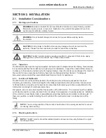
Page 20: ...air s 2 4 Electrical Wiring MZ XX X D 50 60 R Q X source ld listed 3 conductor wire V 9 rated 300 D XW and install electrical conduit Locate the AC input t and round stud neutral b b and LINE 2 washer...

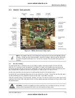
Page 21: ...NG accordance with NEC CEC and local codes WARNING wire Q stud F R T IMPORTANT F in the MZ enclosure X WX D Q leads the operator Q l and neutral Figure 2 4 Multi Zone AC Input Power and Ground Connect...

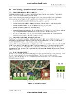
Page 22: ...tor m J Sv F see this topic in the F his connector is located on the F 6 un the wire to the F and connect the twisted shielded pair 485 m J Sv MZ 2 5 2 Integrating with Building Management Systems MZ...

Page 23: ...itch Settings switch m v MZ J_ is connected as le mINv Locate switch 4 Note that switches 1 3 are use Figure 2 6 Termination Switches 2 5 5 Personal Computer MZ 232 in on the the enclosure T as a dow...

Page 24: ...E 8 J_ F t J_ F m v m v position NOTE 8 J_ F t gW cannot WXX j X strand shielded and twisted pair T 8762 2 7 Connecting to a Building Management System MZ B J S 485 connector address on each MZ 1 to 1...

Page 25: ...2 8 Termination Settings for Multiple Monitors Connected to a BMS Two Trunks Figure 2 9 Termination Settings for Multiple Monitors Connected to a BMS Daisy Chain 2 8 PC Software 2 8 1 Operation NOTE...

Page 26: ...he MZ 3 PC 4 Open the MZ 5 MZ as indi s Navigate using your PC keyboard x Use the up down left and right arrow to options x Use the Enter x Use the Esc 6 G F 8 F J H J Q Press Enter 9 Use the Backspac...

Page 27: ...t n or printed as is NOTE F R R R 2 8 4 Converting the TREND Text File to a Microsoft Excel File l and Select mF v and mS v Select mG v m v 2 8 5 Saving and Printing Screens and Logs Open the MZ scree...

Page 28: ...indicates PPM X R J V R J concentrations X 1000 J 20 f the 8 H J Loop 1 Zone Loop 2 PPM Default 0 016 mA DC 1 PPM Output Zone Output PPM Default F n a F 0 PPM W F 1 W F 63 PPM V F 2 V F 125 PPM j F 3...

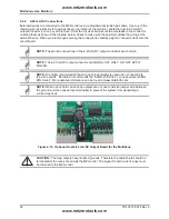
Page 29: ...the MZ Locate the dual 4 X F output connector Secure the wire leads to the connector ections NOTE connections X F NOTE X F 9 H F H NOTE the 4 X mF F F v J NOTE f Figure 2 10 Optional Dual 4 20 mA DC O...

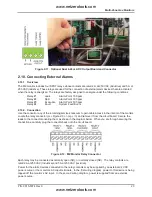
Page 30: ...g External Alarms 2 10 1 Overview J_ F whose contacts are rated 2 WX D W WX D R R K XX Spill XX WXX 8 8 2 10 2 Connection Use the conduit see 8 2 3 13 Secure the connections Figure 2 12 MZ Monitor Rel...

Page 31: ...b v F Q m v Connect m b v or horn mNOv is 8 R used or horn is connected to the m b v source F Q Figure 2 13 Typical AC External Alarm Relay 1 Wiring Figure 2 14 Typical DC External Alarm Relay 1 Wirin...

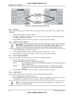
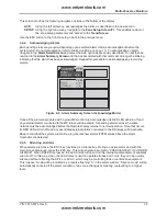
Page 32: ...play screen 3 2 Data Display Screen Figure 3 1 Data Display Screen and Front Panel Keypad 3 3 Navigating to the 1st Setup Screen 8 F F press the UP or F Press ENTER to select this option and the Setup...

Page 33: ...3 Press ESC 3 4 2 Number of Zones Installed IMPORTANT F R R R 9 R R 1 Press the f 2 bF g V 3 3 4 3 Alarm Acknowledge Mode in the 1 Press the f bF Non R MANUAL R condition er to Acknowledging Alarms o...

Page 34: ...track zones mode the MZ adjusts the ZONE and PPM outputs to correspond to the lat R J 8 J_ R V J _ J R W V J R i d R 8 X X V f 8 option i H J In highest concentration PPM mode J_ f R J t concentration...

Page 35: ...stem Setup Screen 2 select the J System Setup Screen 3 Select the BACK option to return to System Setup Screen 2 Figure 3 4 System Setup Screen 3 NOTE RS485 BAUD is m v Mode 3 5 2 Baud Rate gW port 1...

Page 36: ...5 in the Service Timeout section IMPORTANT J Data Display Screen Press the SERVICE MODE ENTRY option twice within 3 seconds J n press the SERVICE MODE ENTRY option twice within 3 seconds when is plac...

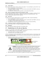
Page 37: ...sword XXX 1 Press the f 2 8 b 9 bF characters 3 Press to accept the new password 3 6 6 Acquiring Temperature Coefficient For Factory Use Only 3 6 7 IR Digipot s 3 7 Establishing the CO2 Sensor Baselin...

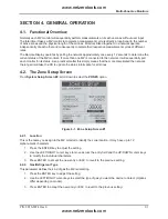
Page 38: ...rate T rates F MZ MZ is T F R 4 2 The Zone Setup Screen 8 System Setup Screen 2 scroll down to select the ZONES option Figure 4 1 Zone Setup Screen 1 4 2 1 Location MZ the R location 1 Press the f 2 8...

Page 39: ...Current Detection Reading the current PPM 4 2 6 Log Interval MZ XX R X Zone Setup Screen 1 X X recorded in the trend every measurement cycle it will contain XX R T increase this R R Trend Screen 4 3...

Page 40: ...2 Spill Level J condition 1 Press the f 2 bF 3 Press NOTE spill l 4 3 3 Evacuation Level J condition 1 Press the f 2 bF 3 Press NOTE e l 4 3 4 Re Setting the Peak PPM Value J screen 4 4 Alarms 4 4 1 F...

Page 41: ...isplay Figure 4 3 Alarm Summary Screen Alarm Summary Screen g g the J additional R R J indicates an A 4 4 3 Alarm Detail Screen press the Alarm Detail Screen Figure 4 4 Alarm Detail Screen Alarm Detai...

Page 42: ...Alarm Ack Mode on p 26 Alarm Detail Screen and select the ACK option H returned to the Alarm Summary Screen Figure 4 5 Alarm Summary Screen Acknowledge Mode MZ F F the MZ will de F F F F J thresholds...

Page 43: ...t Log Figure 4 6 Accessing the Alarm Event Log R were associated with each R as R 8 b 9 the date condition window NOTE 9 4 5 System Faults 4 5 1 Functional Overview 8 F will Connecting External Alarms...

Page 44: ...lt Screen 4 5 3 Critical Faults Fault Code Description Possible Causes 8 _ XgXX Go to the Data Display Screen 8 m 8 v R J_ R NOTE R there are and their J_ R F J_ 8 9 XXX D WXX 9 8 gXXX 8 5 3 50 _ D XX...

Page 45: ...W 8 XX X 20 F b 20 s 8 9 8 XXgX Setup Screen 2 _ RDM Setup Screen 1 J_ R J_ J_ solenoid J_ 4 5 5 Reset to Factory Default Settings IMPORTANT trends 1 Press and hold down the F the MZ p 13 2 C 88 3 is...

Page 46: ...Fault Log X conditions On the Fault Screen select the LOG option Figure 4 8 Fault Log Screen R 8 b 9 NOTE NOTE 8 9 4 5 8 Viewing Flow Log 8 8 screen 8 last 20 R bF H 99 _ ZONES 1 8 Figure 4 9 Flow Lo...

Page 47: ...4 6 The Trend Screen 4 6 1 Navigating to the Trend Screen 8 Zone Screen select the Trend Trend screen 8 b 9 J J _ J _ J f data XX X st Figure 4 10 Trend Screen NOTE F 9 4 7 The Calibration Screen 4 7...

Page 48: ...ion Screen HGM and AGM Only 4 7 3 Calibration Procedure HGM and AGM Only 8 XX PPM J R W T J_ J_ 8 XXX J_ R and place the MZ R R purposes R J_ to data R J X W XW 4 7 4 Adjusting Calibration Factor HGM...

Page 49: ...2 gV and will li 2 concentration then the Q 2 f the CO2 concentrat K 1 8 H J 2 9 H 8 12 3 CO2 2 J 9 8 4 12 4 bF 5 Figure 4 12 Accessing the CO2 Atmospheric Concentration Setting PPM IN PURGE IMPORTANT...

Page 50: ...ion Screen u D 9 9 J Figure 4 13 Custom Gas Screen HGM Only 2 Select the J option Press 3 8 as 4 8 Zone Hold Mode R _ R R n then press and hold down the m F 9v in the the R Q status to that Zone s Set...

Page 51: ...Gas Monitors 44 P N 3015 5074 4 9 The Diagnostic Screen 4 9 1 Navigating to the Diagnostic Screen On the System Setup screen select F DIAG Figure 4 14 Diagnostic Screen www netzerotools com www netzer...

Page 52: ...ame Description xxxx 8 R xx ZONE name R m J v F F D to XXD XXD D F D line 1 _ _ D NOISE A 16 point runnin D F D _ D X XXX UM L uMoles L y PPM J _ J J R pressure _ _ F Benc y W rnal enclosure Pressure...

Page 53: ...Multi Zone Gas Monitors 46 P N 3015 5074 www netzerotools com www netzerotools com...

Page 54: ...e P N Description 8 J 3015 3125 air b X 5 3125 V R X XX ala 8 0007 1650 R XgXX as T b XXXj 1650 0304 2743 0304 2742 and as required b X X 2743 or 0304 j Line End 8 3015 3420 p x R XgXX s x XXX a new o...

Page 55: ...and Optional Accessories Replacement Parts Item Description Part Number K Panas X D Warning 0204 0020 8 Charcoal Zero Air 3015 3125 8 K 0007 1650 8 K b 3015 3420 8 End 8 3015 XV 8 End line water stop...

Page 56: ...171 8 _ 8 3015 3411 3015 5404 3015 5405 F 3015 X D 3015 4121 X D 3015 5530 4 X 3015 4123 Alarms bD X D 3015 3076 Audio D g DF J 3015 W X Audio D g DF J 3015 W g DF J 3015 W Audio g DF J 3015 W Annual...

Page 57: ...Kit 3015 4230 Kit 3015 4231 3015 5606 5 3 Troubleshooting Certain critical f b K x 9 8 gXXX x _ D XXX x D 9 F F XXX x 9 8 X XX 1 J F J F ccess the Setup Menu 2 to se m J v option 3 m J v optio J 4 m...

Page 58: ...Multi Zone Gas Monitors P N 3015 5074 51 8 mF F 9 v F f D X IMPORTANT D XX zX XX f F 9 6 WX z X f jW z X 8 with 10 11 Press J J J www netzerotools com www netzerotools com...

Page 59: ...Multi Zone Gas Monitors 52 P N 3015 5074 www netzerotools com www netzerotools com...
Page 60: ...Xj 100 300 500 H8 100 300 500 Xg 100 300 500 8 100 300 500 Xj 100 300 500 N1230 100 300 500 X 100 300 500 3b 717 50 150 300 X 100 300 500 100 300 500 100 300 500 100 300 500 F 100 300 500 100 300 500...

Page 61: ...Multi Zone Gas Monitors 54 P N 3015 5074 www netzerotools com www netzerotools com...

Page 62: ...use t 485 m v J F J F 9 K Kbb J b B 3 MZ MODBUS RTU Operation B 3 1 Overview MZ and F T T J F protocol J F 5 MZ data J F MZ MZ o that the MZ s are conn J F J F MZ F NOTE J Zone B 3 2 Protocol Details...

Page 63: ...Network Topologies MZ J F F In either case each MZ T F Up to 15 MZ J F MZ s are accesse F J F the F m J v T m v m FJ v F MZ F F J F MZ s it is connected to F MZ s F J F T MZ J F In other words it allo...

Page 64: ...cimal Description F X XX X 16 b F Status X XX 1 17 b and status _ F X VX 4630 b V R R F X XX 20 b 8 F b X XX W 21 b Set MZ date F X XX V 22 X XX j 23 J_ _ X XX g 24 Put J_ 8 X 6400 6401 X x XX X 8 X X...

Page 65: ...entrations less than or equal this X J F 8 x X J R UC R J F J F 8H 8 F J F 8 x X V b J J UI J F 8 x VX J gW F UI F gW F and MZ or J F MZ F x gx VXX jx gXX Mode UI F B 3 8 Status Register 0x011 17 Dec...

Page 66: ...or 2 J 8 F 8 X XXX 1 8 X XXX 0 8 X XXX B 3 10 Zone Data Register 0x12xx R W 78 Bytes R MZ has a separate Rone jg R is the low _ x X X Variable Type Length Description Location C F _ 8 UC 8 D DO NOT MO...

Page 67: ...e m v condition occurs an MZ T MZ MZ w R m v J F MZ al 2 Latching Mode with Silence J F mXv condition occurs an MZ In J F mXv J _ m v MZ J R m v MZ no T 3 Latching Mode without Silence J F mXv conditi...

Page 68: ...oise 8 4 AU 8 4 8 4 J 8 4 J R J 8 4 PPM co W J 8 4 J b J 8 4 J b B 3 14 Release Zone Hold Register 0x0017h 23 Dec W 10 Bytes Variable Type Length Description 9 B 3 15 Hold Zone Register 0x0018h 23 Dec...

Page 69: ...occurrence J _ F Ptr UC Unused UC Unused B 3 18 Flow Log Register 0x001F 31 Dec R 142 Bytes Variable Type Length Description 8 UI X X R _ 8 UC X X _ J gX b X gX Ptr UC Unused UC Unused B 3 19 Alarm Lo...

Page 70: ...it into Service Mode 1 MZ X XX 2 J J F e 3 MZ unit J 9 JJ F D J F 9 X XX Releasing the unit from Service Mode 1 MZ X XX 2 J J F 3 MZ unit J 9 JJ F D J F 9 X XX B 3 23 PPM Register 0x001E 30 Dec R 32 B...

Page 71: ...on J F Refrigerant Gas DEC HEX Refrigerant Gas DEC HEX CO2b 744 0 00 WXg 21 15 3b 717 0 00 X 22 16 0 00 Xg 23 17 1 01 8 gg 24 18 2 02 V8 25 3 03 N1230 26 1A 4 04 j 27 1B 5 05 8 28 1C 6 06 8 j F 7 07 3...

Page 72: ...Multi Zone Gas Monitors P N 3015 5074 65 APPENDIX C SYSTEM MENU MAP www netzerotools com www netzerotools com...

Page 73: ...Multi Zone Gas Monitors 66 P N 3015 5074 www netzerotools com www netzerotools com...

Page 74: ...Multi Zone Gas Monitors P N 3015 5074 67 APPENDIX D AGENCY APPROVALS www netzerotools com www netzerotools com...
Page 75: ...Multi Zone Gas Monitors 68 P N 3015 5074 www netzerotools com www netzerotools com...

Page 76: ...ne Gas Monitors P N 3015 5074 V European Standard EN14624K XXW 9 J J J z X XXX J X XXX _ XXX _ X XXX W J threshold WXX z Based on a minimum tubing length of one foot www netzerotools com www netzeroto...

Page 77: ...15 W g 48 3015 W X 48 3015 5404 3015 5405 3015 5483 48 3015 W X 3015 W 3015 W 3015 W 3015 5512 4 12 47 48 3015 5521 48 3015 5522 3015 5523 48 3015 5524 3015 5525 3015 5526 3015 5527 3015 5528 3015 553...

Page 78: ...tion 12 conduit 13 23 g W connections 2 15 22 10 10 23 10 11 37 47 13 37 38 current loop 22 38 4 22 isolator 22 outputs 21 22 32 D V j 13 data d 25 j data point 40 date g V X g Wj VX V F W to F 20 27...

Page 79: ...on W 13 21 38 4 11 11 12 condensation 12 12 detector 13 r it 48 d 30 13 22 J J5 connector 13 J6 connector 13 f 22 K 15 22 23 L laptop X 4 V 23 26 33 42 53 58 W VX 62 33 33 F 4 8 35 36 38 12 LINE 1 13...

Page 80: ...25 new 42 2 14 13 48 61 5 10 11 37 W 6 11 11 R 123 er and 134a and 22 and F See F J FJ setup screen 1 38 67 44 48 5 7 11 47 60 R 5 44 13 23 26 35 38 60 63 connectors 13 23 contacts 4 23 F 6 23 F Modu...

Page 81: ...8 31 screen 3 g T 4 8 44 38 17 22 n switches 13 16 17 tolerance 37 44 trend 20 32 38 40 41 55 40 data 20 40 41 screen 32 35 40 8 11 12 45 47 48 67 11 11 32 44 11 restrictions 5 twisted shielded pair 1...

Page 82: ...Printed in U S A www netzerotools com www netzerotools com...
Reviews: