background image

Operation 

Fyrite

 InTech


Manual 


42 

0024-9486 Rev 4 

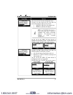
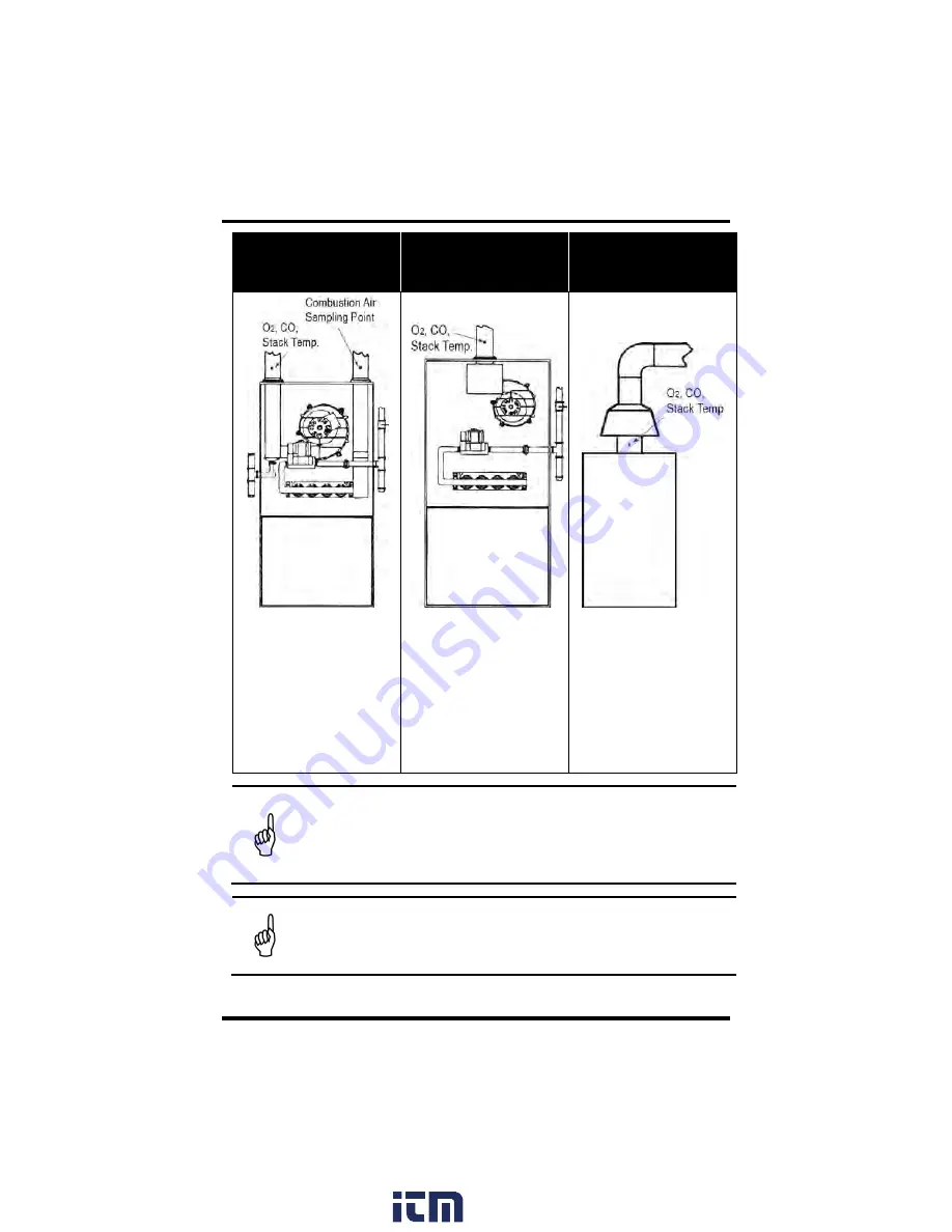
Example 90% Efficiency 

Condensing Furnace 

Example 80% Efficiency 

Fan Assist or Power 

Vented Furnace 

Example 

Atmospheric/Gravity 

Vented Boiler 


Condensing 

furnaces/ 

boilers  can  be  tested 
through  a  hole  drilled  in 
the  plastic  vent  pipe 
(when  allowed  by  the 
manufacturer 

or  local 

authority  of  jurisdiction) 
or taken from the exhaust 
termination. 

Combustion testing of fan 
assist  or  power  vented, 
furnaces/boilers should be 
done  through  a  hole 
drilled 

in 

the 

vent 

immediately  above  the 
inducer fan. 

Boilers, which have a ‘bell’ 
shaped  draft  diverter  on 
top,  should  be  tested 
directly below the diverter 
through  a  hole  drilled  in 
the vent connector. 


IMPORTANT:    Review  manufacturer  recommendations  for  the 
combustion  device  being  tested,  and  be  aware  of  accepted 
practices of the local jurisdiction before introducing sampling holes 
into exhaust pipes or ducts. 


CAUTION:   To avoid the  introduction of dangerous exhaust  gases 
into the space, be sure to completely and securely seal any sampling 
holes made in the exhaust pipes or ducts. 


www.

.com

information@itm.com

1.800.561.8187

Summary of Contents for Fyrite InTech 0024-8510

Page 1: ...Combustion Gas Analyzer Configuration and Operation Manual Instruction 0024 9486 Revision 4 October 2018 Product Leadership Training Service Reliability www com information itm com 1 800 561 8187 ...

Page 2: ...liability and buyer s remedy under this warranty of title are limited to the removal of any title defects or at the election of Bacharach to the replacement of this product or parts thereof that are defective in title THE FOREGOING WARRANTIES ARE EXCLUSIVE AND ARE GIVEN AND ACCEPTED IN LIEU OF I ANY AND ALL OTHER WARRANTIES EXPRESS OR IMPLIED INCLUDING WITHOUT LIMITATION THE IMPLIED WARRANTIES OF ...

Page 3: ...amages in connection with the furnishing performance or use of this material No part of this document may be photocopied reproduced or translated to another language without the prior written consent of Bacharach Inc Copyright 2018 Bacharach Inc all rights reserved BACHARACH Fyrite InTech and B SMART are registered trademarks of Bacharach Inc All other trademarks trade names service marks and logo...

Page 4: ...13 2 2 Front Panel Buttons 14 2 3 Power Options 15 2 4 Turning On the Fyrite InTech 16 Section 3 Configuration 17 3 1 Menu Structure Overview 17 3 2 The Warm up Sequence 17 3 3 Main Menu 18 3 4 Select Fuel Menu 19 3 5 Ambient CO Menu Siegert Only 20 3 6 Memory Options Menu 22 3 7 Setup Menu 24 3 8 Calibration Menu 35 3 9 Diagnostics Menu 36 3 10 Status Menu 38 Section 4 Operation 40 4 1 Prerequisi...

Page 5: ...ed 53 5 4 3 O2 Sensor Replacement Procedure 54 5 4 4 CO Sensor Replacement Procedure 54 5 4 5 B SMART CO Sensor Replacement 55 5 5 T Stack Calibration 56 5 5 1 Materials Required 56 5 5 2 T Stack Calibration Procedure 56 5 6 CO Sensor Calibration 58 5 6 1 Materials Required 58 5 6 2 CO Manual Zero Procedure 58 5 6 3 CO Sensor Span Procedure 59 5 7 T Ref Sensor Calibration 60 Section 6 Troubleshoot...

Page 6: ...ntially hazardous situation which if not avoided may result in minor or moderate injury Caution statements may also be used to alert against unsafe practices IMPORTANT An important statement provides emphasis of an important feature operation etc Failure to follow this information could void your warranty result in improper operation or cause equipment damage NOTE A note statement provides emphasi...

Page 7: ... there is a high emission of soot the probe s sample filter may become clogged Before every use check the filter to confirm it is clean or replace it with a new filter To prevent soot intake and a clogged filter a smoke test should be performed before operating under such conditions This ensures that the furnace or boiler is burning at a level appropriate for the use of this instrument When the CO...

Page 8: ...ed sensor s as ordered and depending on the model and kit some or all of the following rubber boot spare filters Fyrite User Software FUS USB cable type A to mini B Infrared Data Association IrDA printer with four disposable AA alkaline batteries printer paper 1 5 North American NA vs Siegert S Combustion Equations Though the combustion process is fairly standardized across the globe a combustion ...

Page 9: ...9 Different RUN Parameters EFF NA vs Stack loss and ETA S Excess Air NA vs Lambda S Lambda is similar to excess air Extra Siegert Parameters CO CO2 ratio boiler temperature smoke number and oil derivative are displayed for Siegert only CO2 Max Siegert users can set a CO2 max number for the fuel Print Average Feature There is a print average feature for Siegert NOx Filter A NOx filter is included i...

Page 10: ...Fyrite InTech Manual Overview 0024 9486 Rev 4 5 1 6 Components www com information itm com 1 800 561 8187 ...

Page 11: ...Overview Fyrite InTech Manual 6 0024 9486 Rev 4 www com information itm com 1 800 561 8187 ...

Page 12: ...d diagnostic menus p 36 o Manual entry of values Siegert only pp 25 26 o Ambient CO Siegert Only p 48 User Customizations o Combustion Air Temperature T Air source selection p 34 o North American and Siegert combustion calculations pp 32 44 o Multi language interface p 29 o Auto Manual zero functions for the CO sensor p 31 o Customized user information 3 lines of 20 characters p 46 o Customized lo...

Page 13: ...d 36 53 Calibrate as Needed 35 58 Replace Batteries as Needed 15 Filter Replacement 52 Place Probe in Sampling Point 40 Collect Data RUN Button 44 Save Data as Needed F3 14 44 Stop Test HOLD Button 14 44 Print Data as Needed F1 14 44 45 Save Data F3 14 44 Print Data F1 Option 14 44 45 Review All Combustion Data 14 44 45 Adjust Combustion Equipment As Needed Save Data F3 14 44 Purge Instrument 30 4...

Page 14: ...above 18 8 O2 and the stack temperature is not above 650 C 1200 F 1 9 Fyrite InTech Sales Combinations Fuel Equations North American NA Siegert S Final Assembly 0024 7340 0024 7341 0024 7342 Kit Type O2 Only Basic Reporting Basic Reporting Sales Kit P N 0024 8510 0024 8511 0024 8512 0024 8513 0024 8514 Probe X X X X X Batteries X X X X X T Stack X X X X X Manual X X X X X O2 X X X X X CO X X X X F...

Page 15: ...Overview Fyrite InTech Manual 10 0024 9486 Rev 4 www com information itm com 1 800 561 8187 ...

Page 16: ...e Product Approvals and Regulatory Compliance EN50270 CE Mark EMC tested in accordance with European Directive 2004 108 EC EN50379 Standard for portable electrical apparatus designed to measure combustion flue gas parameters of heating appliances Siegert only Parts 1 and 3 RoHS Compliance Case Construction High impact ABS plastic with co molded rubber Protective rubber boot with molded in magnets ...

Page 17: ... 1202 F 1 C 1 F 2 C 0 to 124 C 3 C 125 to 249 C 4 C 250 to 400 C 50 sec Calculation Calculation Range Reso lution Version NA Siegert Efficiency HHV 0 1 to 100 0 1 X X ETA LHV 0 to 115 0 1 X Excess Air 1 to 250 1 X Stack Loss 0 1 to 100 0 1 X Lambda 1 to 9 55 0 01 X CO2 dry basis 0 1 to a fuel dependent max in 0 1 X X CO Ref to O2 0 to 9999 ppm 1 ppm X X CO CO2 Ratio 0 0001 to fuel dependent max 0 ...

Page 18: ...defective replace the entire probe assembly 2 Before using the analyzer check that the water trap filter is clean and dry If necessary dry out the trap and replace the filter element 3 Push the probe s sample gas tubing onto the GAS inlet connector 4 Push the probe s thermocouple into the T STACK connector on the instrument noting the orientation IMPORTANT The T STACK connector tabs are keyed to f...

Page 19: ...d RIGHT arrow buttons jump to the top and bottom of lists respectively LEFT and RIGHT arrow buttons position the active cursor on specific elements of a value to be changed The ENTER button Performs the action selected While in the HOLD screen turns the sample pump on displays the RUN screen and begins a combustion test While intheRUNscreen turns the sample pumpoff displays theHOLDscreenandthelast...

Page 20: ...n Batteries 4 AA Fresh or Fully Charged Estimated Life Span in Hours Continuous Pump On Alkaline disposable 15 hours Lithium disposable 20 hours Rechargeable 8 hours Replace batteries as follows 1 Remove the battery cover from the back of analyzer 2 If old batteries are installed remove them and properly discard them 3 Observing the polarity markings inside the battery compartment install four AA ...

Page 21: ... time 2 4 Turning On the Fyrite InTech To turn on the Fyrite InTech press the PWR button NOTE After turning on the Fyrite InTech it performs a warm up procedure which includes an auto zero procedure for the sensors see pages 17 and 31 For this reason be sure to turn on the Fyrite InTech in a clean air environment www com information itm com 1 800 561 8187 ...

Page 22: ...em are described in a top down fashion starting from the startup screens and working sequentially through the menus and menu items 3 2 The Warm up Sequence Boot Screens Description Splash screen shows the Bacharach logo with version model number and serial number information This screen is displayed for approximately 3 seconds A warm up screen is displayed during which the instrument is purged and...

Page 23: ... max CO Access the Memory Options Menu see page 22 Access previously saved test results Delete all previously saved test results Access the Setup Menu see page 24 Edit view instrument preference Edit view system parameters Edit view combustion test parameters Access the Calibration Password Screen and the Calibration Menu see page 35 Calibrate sensors Access the Diagnostics Menu see page 36 View r...

Page 24: ...ombustion fuel from the fuel list Use the UP and DOWN arrow keys to highlight the desired fuel and use the ENTER key to select NA Fuel List Siegert Fuel List Natural Gas Natural Gas Oil 2 KOKS Oil 6 LEG Propane Propane Kerosene Oil 2 B5 Oil 6 Coal Biofuel LPG Butane www com information itm com 1 800 561 8187 ...

Page 25: ...ycle during which a status screen is displayed It shows the starting ambient CO value the current CO value and the elapsed time into the test NOTE Press the F2 key to cancel a test in progress After the test is complete the Ambient CO Summary screen is displayed This is a scrollable window that shows the 16 CO snapshot readings as well as the maximum CO reading that was sampled during the entire t...

Page 26: ...g F1 and saved to memory with a time and date stamp by pressing F3 Press F2 to return to the menu NOTE If the ambient CO results are saved to memory they are not included as part of the Print Average feature NOTE Any over range CO values e g CO 2000 ppm are displayed as xxx www com information itm com 1 800 561 8187 ...

Page 27: ...ved combustion tests starting at 1 NO DATA is displayed if no tests were saved since the last time that memory was cleared To view saved data use the UP and DOWN arrow keys to highlight the desired test from the list Press the ENTER button to display the saved data Prompts user before clearing all saved combustion tests from memory www com information itm com 1 800 561 8187 ...

Page 28: ... 3 samples highlighted Use the UP and DOWN arrow buttons to move the scrolling window up and down to select which three contiguous samples are to be averaged then press ENTER The average is calculated displayed and available for printing left If fewer than 3 samples exist the average is not calculated right www com information itm com 1 800 561 8187 ...

Page 29: ...e and display an average smoke value based on 3 smoke test results that are entered by the user A sample smoke scale is shown below Perform 3 smoke tests then enter the results in the 3 smoke number parameters shown below Use the UP and DOWN arrow buttons to highlight smoke number 1 2 or 3 then press ENTER Use the LEFT and RIGHT arrow buttons to set the smoke number 0 9 that most closely matches t...

Page 30: ...e gas AFTER the combustion process is adjusted and the smoke test indicates a smoke level of 0 or 1 Oil Derivative Siegert only specifies whether or not oil derivatives were present during the smoke tests see page 24 For incomplete combustion oil derivatives present in the sample can be precipitated onto the filter paper causing a color change in the smoke spot Use the UP and DOWN arrow buttons to...

Page 31: ... Use the LEFT and RIGHT arrow buttons to select the desired field to edit Then use the UP and DOWN arrow buttons to change the values of the selected field Press ENTER to save new date and time Press ESC to quit without saving NOTE See DATE FORMAT option in SETUP MENU to select either MM DD YY format or DD MM YY format for North American configurations only NOTE Siegert configurations display time...

Page 32: ...by default if Siegert configuration or by choice through the Date Format parameter if North American configuration The measured value of CO can be referenced to a specific O2 percentage 0 to 15 as referenced in the equation below 𝐶𝑂 𝑛 20 9 𝑂2 𝑅𝑒𝑓𝑒𝑟𝑒𝑛𝑐𝑒 20 9 𝑂2 𝑀𝑒𝑎𝑠𝑢𝑟𝑒𝑑 𝐶𝑂 Use the UP and DOWN arrow buttons to enter the O2 reference value n from 0 to 15 Press ENTER to save the selection or ESC to re...

Page 33: ...a row and press ENTER to begin editing the selected row Then use the UP and DOWN arrow buttons to select the desired letter number or special character for the current text position SPACE a z A Z 0 9 Use the LEFT and RIGHT arrow buttons to move the cursor horizontally on the selected row and repeat the character selection process for each text position When finished press ENTER to save the row s c...

Page 34: ...rument model Use ENTER to enable the selected language NOTE The number of available languages may differ based on the combustion equation setting Three languages are available for North American NA configurations and eight languages are available for Siegert S configurations Refer to the table below and the SETUP MENU for more information English French Spanish German Italian Danish Polish Dutch N...

Page 35: ... cancels the automatic shutdown that is the instrument remains ON and restarts the timeout countdown if any key is pressed CO is greater than 50 ppm or O2 is less than 18 8 Provides a list from which the user may chose a minimum purge duration time minimum length of time that the pump continues to run after shutdown is initiated Use a longer Post Purge Period if the Fyrite InTech has been exposed ...

Page 36: ...is parameter is only available in North American configurations Use the UP and DOWN arrow buttons to highlight the desired date format Press ENTER to save new date format Press ESC to quit without saving Provides a list from which the user may select the desired method for zeroing the CO sensor Auto Zero happens automatically at warm up Manual zero is used to initiate the zeroing process whenever ...

Page 37: ...re a manual zero for the CO sensor The instrument uses the stored value to indicate background CO values after warm up instead of performing an auto zero on the background gas The COMBUSTION EQUATIONS menu allows the user to select either Siegert combustion equations or North American combustion equations Use UP and DOWN arrow buttons to highlight the desired option Press ENTER to select www com i...

Page 38: ...chemical sensor whose lifespan is a function of its exposure to the target gas CO in this case Though the CO sensor is designed to be used in combustion environments having a fairly wide range of CO gas present limiting unnecessary overexposure to CO gas can greatly increase the life expectancy of the CO sensor In addition it can shorten sensor recovery time after exposure The Protect CO feature s...

Page 39: ... begins enforcing the current Protect CO threshold limit again Purge Option Remove probe tip from flue and press ENTER Pump starts Purge begins Measured CO is displayed Purge ends when CO level drops below 50 ppm The Combustion Air Temp option allows you to select a source for the combustion air temperature T Air used by the analyzer for calculations There are 3 choices 1 T Air value is read dynam...

Page 40: ...ted the user must enter a 4 digit numeric security code in order to proceed to the calibration options The default password is 1111 Use the UP and DOWN arrow buttons to scroll through numerals 0 9 until the desired numeral is reached Press ENTER to advance to the next position of the password Press ENTER after all four digits are set Press ESC to return to the SETUP MENU NOTE The calibration passw...

Page 41: ...ement sensors of the instrument Displays the estimated oxygen O2 sensor life based on the sensor s 3 digit date code that you enter from the label on the sensor the current date that you set the typical O2 sensor life of approximately 24 months The Fyrite InTech will show that the O2 sensor needs to be replaced and an error message is displayed see below www com information itm com 1 800 561 8187 ...

Page 42: ...ween the 2 digit month code 00 12 and the one digit year code 0 9 corresponding to the last digit of the manufacture year that make up the 3 digit date code Use UP and DOWN arrow buttons to increment and decrement the selected field s value When finished press ENTER to save the changes NOTE Entering a value of 000 three zeros disables this feature Next verify the current month and year Use the arr...

Page 43: ...r the typical O2 life span 2 years the output of the sensor NOTE If either of the entered values is incorrect the status of your O2 sensor life will not be accurate Actual sensor life may vary Displays fresh air diagnostics similar to the display at warm up After the warm up countdown any detected errors are displayed Otherwise a Success message is displayed 3 10 Status Menu www com information it...

Page 44: ...4 39 Status Menu Function This is the device status screen which displays information about the device Some of the information displayed on this screen includes serial number firmware version model number etc www com information itm com 1 800 561 8187 ...

Page 45: ...argeable batteries the warm up process has completed in fresh air without interruption or errors 4 2 Sampling Point Examples WARNING The illustrations of combustion devices and sampling points in this section are examples only Be sure to consult with the manufacturer s documentation for the combustion devices you are servicing The following combustion devices and example sampling points are shown ...

Page 46: ...r design test each of the exhaust ports at the top of the heat exchanger The probe should be inserted back into each of the exhaust ports to obtain a flue gas sample before any dilution air is mixed in Domestic hot water tanks with the bell shaped draft diverter can be accurately tested by inserting the probe tip directly into the top of the fire tube below the diverter www com information itm com...

Page 47: ...s should be done through a hole drilled in the vent immediately above the inducer fan Boilers which have a bell shaped draft diverter on top should be tested directly below the diverter through a hole drilled in the vent connector IMPORTANT Review manufacturer recommendations for the combustion device being tested and be aware of accepted practices of the local jurisdiction before introducing samp...

Page 48: ...orner of the display and hear the sample pump turn on If you see the word HOLD press the RUN HOLD button again 5 Monitor the display for combustion data 6 If desired turn on your optional IrDA printer then press the F1 button on the Fyrite InTech to print the current combustion data 7 Press the F3 button as desired to save combustion data for later retrieval review and or printing 8 Press the RUN ...

Page 49: ...nction to complete you will hear the pump stop and the display will shut off Use the results of your combustion testing to assist in diagnosing any issues or potential issues that may exist with the combustion system WARNING CO gas is life threatening and part of all combustion processes Be sure to thoroughly evaluate systems and take ALL appropriate actions to maintain life safety 4 4 The RUN Scr...

Page 50: ...trument has the ability to store recall to the display and print sets of time and date coded test records The time and date are set through software menu selections Displaying stored records is done through the MEMORY DIRECTORY MENU Press F1 to print displayed test records Step Example Printing Procedure Using Optional IrDA Printer 1 Fyrite InTech should be turned on and displaying a screen with a...

Page 51: ...nes of 20 characters for user information This information will appear with test records when they are printed User name and optional information are entered via software menu selections in the SETUP MENU or via the Fyrite User Software FUS www com information itm com 1 800 561 8187 ...

Page 52: ...anual Operation 0024 9486 Rev 4 47 IR Communications Settings Baud Rate 9600 Data Bits 8 Stop Bits 1 Parity None Protocol IRDA SIR Distance 8 16 in 20 41 cm Angle 60 maximum www com information itm com 1 800 561 8187 ...

Page 53: ... saved to memory and or printed Use the following procedure to perform an ambient CO measurement Step Example Procedure for Taking Ambient CO Measurements 1 Turn on the InTech in a fresh air environment and wait for initialization to complete 2 Verify successful initialization no errors 3 Check battery status see page 15 If battery life is questionable replace the batteries as the Ambient CO test ...

Page 54: ...ser Software A PC with Fyrite User Software FUS installed can set edit and transfer the following instrument time and date calibration password time meters B SMART code user name instrument settings customer logo firmware updates language www com information itm com 1 800 561 8187 ...

Page 55: ...nto service Field calibration is also possible with the proper equipment Refer to the calibration section for more information 5 2 Cleaning the Probe The probe tube and gas sample hose will become dirty under normal use NOTE The water trap s filter element should prevent soot from reaching the analyzer s internal components If the probe is not kept clean it could become clogged and restrict the fl...

Page 56: ...astic components Take precautions not to spray cleaner onto the probe handle or analyzer 2 Insert the plastic spray tube of the carburetor cleaner into the gas sample hose and then liberally spray carburetor cleaner through the hose and out the probe tube 3 After spraying remove all the residual cleaner by repeatedly flushing the gas hose and probe tube with alcohol 4 Wipe off the surfaces of the ...

Page 57: ...Calibration and Maintenance Fyrite InTech Manual 52 0024 9486 Rev 4 5 3 Water Trap and Filter Replacement www com information itm com 1 800 561 8187 ...

Page 58: ...or Replacement NOTE The O2 sensor life is approximately 2 years The CO sensor life is greater than 3 years 5 4 1 Accessing the Sensors 5 4 2 Material Required As Needed O2 Sensor P N 0024 0788 CO Sensor P N 0024 7265 or B Smart sensor P N 0024 1467 www com information itm com 1 800 561 8187 ...

Page 59: ... ribs on the sides of the sensor with the corresponding shape in the base Inserting the pins into the connectors in the base 8 Reattach tubing Close battery door Turn on instrument 9 After warm up completes enter the 3 digit date code see page 36 5 4 4 CO Sensor Replacement Procedure Follow the procedure below for CO sensor replacement Step CO Sensor Replacement Procedure 1 Remove battery door and...

Page 60: ... Smart Press ENTER to display the B Smart code screen 3 Use the UP and DOWN arrow buttons to enter the 10 digit alphanumeric code supplied with the pre calibrated B SMART sensor Use the LEFT and RIGHT arrow buttons to move the cursor across the screen Press ENTER NOTE If the correct code was entered the analyzer accepts it and returns to the CALIBRATION MENU If an incorrect code was entered the sc...

Page 61: ... Required Thermocouple simulator K type Range 0 to 600 F 18 to 316 F Accuracy 0 5 F 0 3 C Alternatively ice water boiling water thermometer 5 5 2 T Stack Calibration Procedure Step T STACK Calibration Procedure 1 Plug the simulator into the T STACK connector located at the bottom of the analyzer Alternatively Plug the probe s thermocouple into the T STACK connector located at the bottom of the ana...

Page 62: ...sage Applied Value High or Low to appear at the bottom of the screen 5 Wait until the Measured reading stabilizes and then press ENTER to calibrate the TS Zero Measured value to that of the Applied value after which the message Good Calibration should briefly appear followed by the CALIBRATE TS SPAN screen 6 Set thermocouple simulator to 572 F 300 C and then use the UP DOWN LEFT and RIGHT arrow bu...

Page 63: ...manual zero feature see page 31 To perform a manual zero follow the steps below If your instrument is configured for CO auto zero then skip this CO manual zero procedure and go to the CO Sensor Span procedure that follows Step Manual CO Zero Procedure 1 If not already done turn ON the analyzer and display the Main Menu screen 2 Use the UP and DOWN arrow buttons to select the SETUP menu and press E...

Page 64: ...s however the calibration range is from 20 to 1 000 ppm An attempt to calibrate outside this range will cause the message Applied Value High or Low to appear at the bottom of the screen 3 Attach a 500 ppm CO cylinder to the regulator and connect calibration kit components as shown below Apply 500 ppm carbon monoxide in an air balance calibration gas 4 Wait until the Measured reading stabilizes and...

Page 65: ...e InTech Manual 60 0024 9486 Rev 4 5 7 T Ref Sensor Calibration The T Ref sensor is located inside the instrument Calibration is done at the factory and should not need to be done in the field www com information itm com 1 800 561 8187 ...

Page 66: ...or may need to be replaced in the near future Low Battery Battery voltage is low Replace the batteries Applied Value High Low An attempt was made to calibrate a sensor outside its range either above High or below Low the acceptable range Warm up Sensor Error CO sensor was not zeroed at warm up because of high output Run instrument on fresh air then restart instrument to re zero sensor If the messa...

Page 67: ... to operate with the sensor in error however information dependent on the sensor in error is not displayed 6 2 Replacement Parts Part Number Description 0024 0788 O2 sensor 0204 0004 Battery AA Alkaline 0024 7265 CO sensor 0024 1504 NOx filter Siegert only 0024 1467 B Smart CO sensor 0019 7111 Probe and hose assembly North America version 0019 7145 Probe and hose assembly Siegert version 0019 3265...

Page 68: ...7 Thermocouple temperature stack K type 10 feet long 0024 7059 CO Calibration kit no gas 0024 0492 CO calibration gas 500 ppm CO 0051 1994 CO calibration gas 100 ppm CO 0024 1470 PC Software Installer CD 0104 4032 USB cable A to Mini B 0024 1461 Boot rubber 0024 1505 NOx filter kit 0024 1492 Reporting kit 0024 0865 Hard carrying case 0019 3037 Probe stop 0024 8555 Optional Appliance Kit for Ambien...

Page 69: ...fication A label on the back of the instrument provides the following information that is useful for service and troubleshooting manufacturer country of origin certification s part number serial number North American Label Siegert Label www com information itm com 1 800 561 8187 ...

Reviews: