H25-IR PRO Instruction Manual
Maintenance
P/N: 3015-5678 Rev 6
93
Step
Description
instrument.
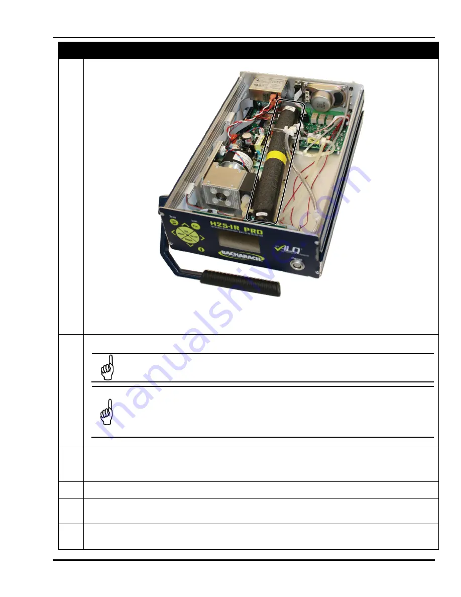
Figure 6-5. NDIR Sensor Showing Three Cable Ties Removed
5
Carefully remove tubing and electrical connectors from old NDIR sensor.
NOTE:
The connection at the back of the NDIR sensor includes a reusable tubing clamp. The clamp
is opened by gently prying the ratcheting jaws away from each other (side to side).
IMPORTANT:
Note the position of the cable ties around the NDIR sensor. The rear cable tie secures
the NDIR sensor and the tubing. The cable tie passes over a tubing connector to prevent the tubing
from being restricted. It is important that the replacement cable tie reproduce the condition at
assembly. The middle cable tie is used to route the tubing and is also not fully tight. All three cable
ties are not to be fully tightened –
DO NOT compress the foam insulation excessively
.
6
Place new NDIR sensor inside chassis, positioning its 10-pin electrical connector toward the rear of the
instrument. Rotate the sensor so that its gas inlet and outlet fittings and its electrical connectors are positioned
as shown in Figure 6-6.
7
Remove protective caps from the gas inlet and outlet fittings of the new NDIR sensor.
8
Connect the 12-conductor ribbon cable from IR SOURCE connector J5 on main board to IR SENSOR EMITTER
connector (front of instrument).
9
Connect the 10-conductor ribbon cable from DET connector J6 on main board to IR SENSOR DETECTOR
connector (rear of instrument).
Summary of Contents for H25-IR PRO
Page 6: ...H25 IR PRO Instruction Manual vi P N 3015 5678 Rev 6 ...
Page 8: ...H25 IR PRO Instruction Manual viii P N 3015 5678 Rev 6 ...
Page 39: ...H25 IR PRO Instruction Manual Menu System Overview P N 3015 5678 Rev 6 29 ...
Page 109: ...H25 IR PRO Instruction Manual Maintenance P N 3015 5678 Rev 6 99 ...
Page 120: ...H25 IR PRO Instruction Manual Declaration of Conformity P N 3015 5678 Rev 6 110 ...


