HGM-MZ to N2 Communications Adapter
4
Rev 1 (P/N 3015-5514)
4. Setting the HGM Communications Address on the Adapter
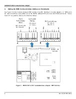
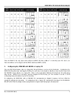
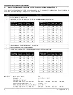
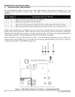
See Figure 3 for the location of adapter DIP switches A and B. Switches 5-8 on the adapter’s ‘A’ DIP switch
are used to match the node address set on the HGM’s address DIP switch (on the HGM main board). Values
from 0-15 are possible. Refer to the table that follows.
Figure 3 – HGM-MZ to N2 Communications Adapter: DIP Switches

