background image

Instruction 3015-4149 

11 

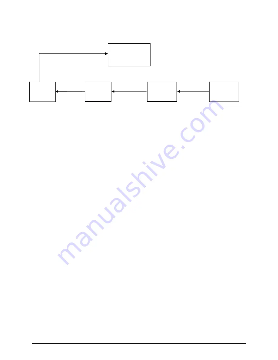
Multiple HGM’s Connected to a Building Management System 

Daisy Chain Fashion 


       RS-485 


         TERMINATOR “IN” 


TERMINATOR 


TERMINATOR 

  TERMINATOR   

          TERMINATOR 

     “OUT” 


       “OUT”  


      “OUT” 


                   “IN” 


HGM300 
UNIT 1 
NODE 1 

HGM300 
UNIT 2 
NODE 2 

HGM300 
UNIT 3 
NODE 3 

HGM300 
UNIT 4 
NODE 4 

BUILDING 

MANAGEMENT 

SYSTEM 

Summary of Contents for HGM300

Page 1: ...c HGM300 RDM800 monitor system connections SECTION 5 Page 10 Multiple HGM connections SECTION 6 Page 12 Powering up the monitoring system SECTION 7 Page 13 Programming the HGM300 using the RDM800 SECT...

Page 2: ...s that is number of zones AC input voltage and dual 4 20ma DC option if ordered RDM800 Remote Display Module if ordered Charcoal filter with T bolt bracket line end filter assembly Quantity dependant...

Page 3: ...ne the best locations The smoke test would provide the pattern of air currents present in the mechanical room The RDM800 should be mounted outside of the mechanical room or at least just inside of a d...

Page 4: ...tor Terminator Switch 4 20 mAdc Interface Board Optional Factory Default Switch Relay Connector Leak Spill Evac Fault Ground Stud AC IN Connector T1 Location of AC Input Line Filter 230 VAC Units Only...

Page 5: ...Instruction 3015 4149 5 RDM800 Components Terminator Switches RS 485 to HGM300 Monitors RS 485 to Building Management System Relay Connector AC IN Connector T3...

Page 6: ...Both loops must be wired if this option is installed If only one loop is used the unused loop must have a jumper wire installed Connect 120 230 VAC power to the RDM800 by removing the four screws hol...

Page 7: ...RELAYS 5 AMP 240 VDC B A GND RS 485 OPTIONAL DUAL LOOP 4 20 mADC COMMON COMMON LOOP 1 ZONE LOOP 2 PPM SPECIAL NOTE TO ESTABLISH THE RS 485 COMMUNICATION LINK WITH THE RDM800 OR WITH A BUILDING MANAGEM...

Page 8: ...R DEFINABLE RS 485 TO HOST SPECIAL NOTE TO ESTABLISH THE RS 485 COMMUNICATION LINK WITH THE RDM800 OR WITH A BUILDING MANAGEMENT SYSTEM USE 18 GAGE AWG MULTI STRANDED SHIELDED AND TWISTED PAIR INSTRUM...

Page 9: ...the Common on the relay block Connect one end of strobe or horn to the NO of whichever level of alarm is appropriate for application The other end of strobe or horn is connected to the Line of the au...

Page 10: ...ement System Note that Building Management Systems set to a 0 or 1 address both respond to messages from the RDM800 as address 1 therefore you should not have a unit set to 0 and another set to 1 on t...

Page 11: ...ted to a Building Management System Daisy Chain Fashion RS 485 TERMINATOR IN TERMINATOR TERMINATOR TERMINATOR TERMINATOR OUT OUT OUT IN HGM300 UNIT 1 NODE 1 HGM300 UNIT 2 NODE 2 HGM300 UNIT 3 NODE 3 H...

Page 12: ...essed Contact the factory if they do not chirp DO NOT plug the gas sample inlets of any unused zones During start up the software will pull a vacuum test to verify the number of zones and a plugged zo...

Page 13: ...sure STP which is 1 atmosphere and 25 degrees C This function is rarely if ever used The PPM readings displayed are inversely related i e as temperature goes up PPMs decrease to the temperature of the...

Page 14: ...splayed for this zone This key is used to clear the peak PPM for this zone which is displayed at the top of this screen The peak PPM gives the PPM level time and date of the highest refrigerant readin...

Page 15: ...rface cable to PC and RS 232 port on the HGM300 3 Insert software disk into PC 4 Open the HGM300 software using Windows Explorer 5 Upon start up the program will immediately attempt to download data f...

Page 16: ...a Saved Program to an HGM300 Open the HGM300 PC software open the proper saved program connect the PC to the HGM300 go to HGM SEND SETUP and then press ENTER The saved program will be sent to the HGM...

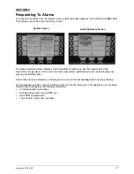
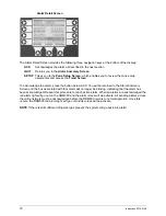
Page 17: ...m If there are more then eight alarms additional screens can be displayed by pressing the MORE button Each active alarm is indicated by a blinking box As an alarm is acknowledged the box stops blinkin...

Page 18: ...ned to the Alarm Summary Screen and the box associated with that alarm will no longer be blinking indicating that the alarm has been acknowledged Repeat this procedure for each active alarm When all a...

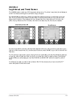
Page 19: ...utes the trend is recorded every time the zone is sampled From the top level Zone Screen press the button adjacent to the zone that you wish to work with to go to that zone s Zone Setup Screen 1 and t...

Page 20: ...FAULT The detector voltage may be out of tolerance Check the Diagnostic Screen for the DET voltage AVE voltage and ZERO voltage Call the factory with this information for further instructions REZERO...

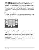
Page 21: ...onnector Check for an illegal parameter If necessary reset to the factory default settings Viewing the Fault Log From the Fault Screen press the button under LOG This screen lists the last 20 fault co...

Page 22: ...me range as line 1 LINE 4 Noise This is a 16 point running average of the noise portion of IR bench output This reading is valuable mainly when refrigerant is NOT present LINE 5 Average Absorbency Thi...

Page 23: ...temperature along with the raw voltage from the temperature sensor and has the same range as line 9 LINE 11 Pressure This is the current absolute manifold pressure in PSIA along with the output voltag...

Page 24: ...Hunt Valley Circle New Kensington PA 15068 WARRANTY HIGHLIGHTS PLEASE REVIEW COMPLETE WARRANTY CONDITIONS PARTS 2 YEARS AFTER SHIPMENT FROM FACTORY UNLESS OTHERWISE NEGOTIATED LABOR 90 DAYS AFTER SHI...

Reviews: