MGS-150 Manual
16
6309-9000 Rev 2
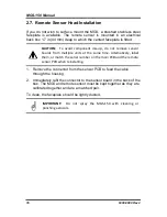
2.7. Remote Sensor Head Installation
If you do not wish to surface mount the MGS, a brushed stainless steel
faceplate is available. The remote sensor is mounted in an electrical
back box 1.7 in (44 mm) deep to which the vented faceplate is fitted.
CAUTION: To avoid component mix-up, do not remove sensor
boards from multiple units at the same time. Alternatively, label
them, or match the serial number on the main PCB and the remote
sensor PCB when reinstalling.
1. Remove the connector from the sensor PCB to feed the cable
through the housing.
2. Immediately refit the connector to the sensor board in the back of the
box. The MGS and remote sensor must be kept together as they are
calibrated together and are a matched pair.
To clean, the faceplate should be lightly dusted.
IMPORTANT: Do not spray the MGS-150 with cleaning or
polishing aerosols.
Summary of Contents for MGS-150
Page 10: ...MGS 150 Manual 10 6309 9000 Rev 2 Figure 2 EC or IR Sensor Components and Wiring...
Page 11: ...MGS 150 Manual 6309 9000 Rev 2 11 Figure 3 SC Sensor Components and Wiring...
Page 18: ...MGS 150 Manual 18 6309 9000 Rev 2 Figure 5 IP66 Housing with Splashguard...
Page 33: ...MGS 150 Manual 6309 9000 Rev 2 33...
Page 34: ...MGS 150 Manual 34 6309 9000 Rev 2...


