Instruction 0024-9448
1-11
Introduction
1.7 Caution: Possible Need for Smoke Test
CAUTION:
When the instrument is used in an inefficient furnace or boiler
application, where there is a high emission of soot, filter may become
clogged. Check filter before every use to confirm that it is clean for use
or replace with a new filter. To prevent this from occurring, a smoke test
should be performed before operating under such conditions to ensure that
the furnace is burning at a level appropriate for the use of this instrument.
Instruction 24-9448
6-12
Maintenance
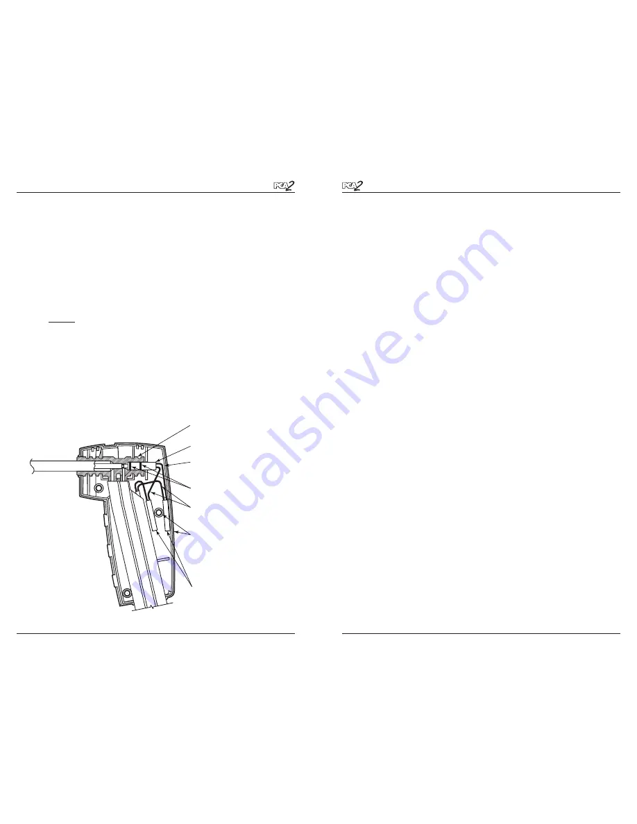
3. Pull old thermocouple from probe body and discard.
4. The new thermocouple has been coiled for shipping purposes.
Straighten the thermocouple using your thumb and index finger.
5. If not already done, install supplied O-Rings onto thermocouple.
6. Insert thermocouple into probe body until it “bottoms out.”
7.
Strip
1
/
4
inch of insulation from each of the probe’s thermocouple
connector wires.
IMPORTANT:
In Step 8, the thermocouple wires must first be
twisted together and then crimped.
8.
Twist
both red thermocouple wires together; insert them into the sup-
plied wire-splice connector; and then crimp the connector using a pair
of pliers. Repeat this step for the yellow thermocouple wires.
9. Reassemble the probe handle, being careful not to pinch the thermo-
couple wires between the handle pieces. In addition, ensure that the
end of the thermocouple is in front of the rib molded into the bottom
handle piece; otherwise, the handle pieces will not fit tightly together.
Figure 6-7. Thermocouple Installation and Wiring
O-Rings
Thermocouple Assembly
Ensure end of Thermocouple is
in front of plastic rib in handle
Wire-Splice Connectors
Red and Yellow
Thermocouple Wires
Cut away view of Thermocouple
inserted into Probe Body
When reassembling probe
handle, ensure that the thermo-
couple wires do not become
pinched around screw hole or
edge of handle


