background image

PCA

Instruction 24-9351

4-14

Operation

4.11 Memory to PC Screen

(For ‘Advanced’ PCA Models 40, 45, 50, 55, 60 & 65)

        MEMORY TO PC

«TRANSMIT DATA

 CLEAR MEMORY

The Memory To PC Screen is displayed by repeatedly pressing the 

MENU


key

from the Combustion Test Screen. Use this screen to either transmit all
stored memory locations to a computer, or clear all memory locations.

TRANSMIT DATA

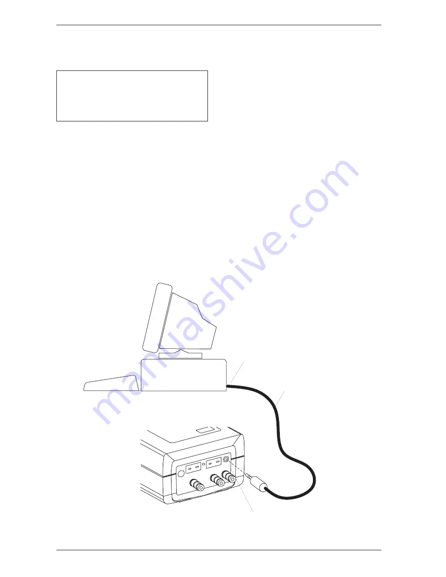
Before data can be transmitted to a personal computer, the PCA’s RS-232
output must first be connected to an unused COM port on the computer
using serial data cable Part No. 24-1073 (see Figure 4-4).  Also, a commu-
nications program (i.e., ProcommPlus

®

, Windows 3.x Terminal, or Win-

dows 9x Hyper Terminal) must be installed, and its communications
parameters configured for: 9600 baud, 8 data bits, 1 stop bit, no parity,
and no handshaking.

Figure 4-4. Connecting the Serial Data Cable

R S - 2 3 2   C o n n e c t o r

A t t a c h   D B 9   C o n n e c t o r   t o   c o m p u t e r ' s  

C O M 1   o r   C O M 2   p o r t .   I f   n e c e s s a r y ,  

u s e   a   2 5 - p i n   t o   9 - p i n   a d a p t e r .

G A S

R E S E

T

P O W E

R

T - S T A

C K

T - A I R

S e r i a l   D a t a   C a b l e

P a r t   N o .   2 4 - 1 0 7 3

Summary of Contents for Portable Combustion Analyzer 24-9351

Page 1: ...on Analyzer PCA INSTRUCTION 24 9351 Operation Maintenance Rev 11 May 2004 M E N U P C A O 2 4 0 C O 1 2 H L D C 2 9 5 C U 1 5 N G T L 2 0 0 T A 1 9 0 P q A 8 1 L A 1 2 4 S Product Leadership Training Service Reliability ...

Page 2: ...TATION THE IMPLIED WARRANTIES OF MERCHANTABILITY AND FITNESS FOR A PARTICULAR PURPOSE AND II ANY OBLIGATION LIABILITY RIGHT CLAIM OR REMEDY IN CONTRACT OR TORT WHETHER OR NOT ARISING FROM BACHARACH S NEGLIGENCE ACTUAL OR IMPLIED The remedies of the Buyer shall be limited to those provided herein to the exclusion of any and all other remedies including without limitation incidental or consequential...

Page 3: ...2 Installing Probe in the Stack 4 4 4 3 3 Performing a Combustion Test 4 5 4 3 4 Ending a Combustion Test 4 5 4 3 5 Turning Off the Analyzer and Purging the CO Sensor 4 6 4 4 Differential Pressure Measurement 4 7 4 5 Warm up Screen 4 8 4 6 Sensor Status Screen 4 9 4 7 Combustion Test Screen 4 10 4 8 Fuel Selection Screen 4 11 4 9 Draft Screens 4 12 4 10 Memory Directory Screen 4 13 4 11 Memory to ...

Page 4: ...eaning the Probe 6 4 6 4 Water Trap Filter Assembly Maintenance 6 5 6 5 Replacing the Particulate Filter 6 6 6 6 Replacing the Oxygen Sensor 6 7 6 7 Replacing the Nitric Oxide Sensor 6 8 6 7 1 Replacing the Nitric Oxide Sensor Filter 6 8 6 7 2 Replacing the Nitric Oxide Sensor Bias Battery 6 9 6 8 Replacing the Carbon Monoxide Sensor 6 10 6 8 1 Replacing the Carbon Monoxide Sensor Filter 6 11 6 9 ...

Page 5: ...tion efficiency analyzer that is designed for continuous on demand sampling of light industrial and residential furnaces appliances and boilers The basic instrument is supplied with a probe instruction manual batteries and carrying case Figure 1 1 PCA 1 1 Introduction M E N U P C A O 2 4 0 C O 1 2 H L D C 2 9 5 C U 1 5 N G T L 2 0 0 T A 1 9 0 P q A 8 1 L A 1 2 4 S ...

Page 6: ...in Flue Gas Carbon Monoxide Content referenced to 0 Oxygen in ppm For analyzers having a Carbon Monoxide sensor Flue Gas Nitric Oxide Content referenced to 0 Oxygen in ppm For analyzers having a Nitric Oxide sensor The standard fuels are Natural Gas Oil 2 Oil 6 LPG Koks Low Energy Gas P Coal available in English German Dutch French Italian Polish and Spanish languages Biofuel available in Danish F...

Page 7: ...described above these instruments have the added capability of measuring displaying and saving Carbon Monoxide CO content as well as calculating CO refer enced to 0 Oxygen PCA 25 55 with Draft and CO Measurement These instruments combine the features of all the PCAs listed above PCA 30 60 with CO and Nitric Oxide Measurement In addition to the features of the basic PCAs with CO measurement these i...

Page 8: ...ocol Advanced PCA Model Features Advanced models of the PCA contain the following features that are in addition to the features of their corresponding standard PCAs 100 memory locations RS232 output for transferring saved data to a Personal Computer Ability to enter three lines of user identification information that is printed at the top of each printout Ability to enter three lines of customer i...

Page 9: ... fuel dependent maximum value in percent Lambda in the range of 1 to 9 95 Carbon Monoxide content referenced to 0 Oxygen in the range of 0 to 9 999 ppm on analyzers equipped with a CO sensor Nitrix Oxide content referenced to 0 Oxygen in the range of 0 to 9 999 ppm on analyzers equipped with a NX sensor Standard Fuels Available for Combustion Calculations Natural Gas Koks LEG LPG Oil 2 Oil 6 P Coa...

Page 10: ... 5 of reading or 5 ppm whichever is greater Flue Gas Temp 2 ºC between 0 and 124 ºC 4 ºF between 32 and 255 ºF 3 ºC between 125 and 249º C 6 ºF between 256 and 480 ºF 4 C between 250 and 400 C 8 ºF between 481 and 752 ºF Ambient Temp 1 C between 0 and 100 C 2 ºF between 32 and 212 ºF Pressure 2 of reading or 0 05 mb 0 02 inches of Water Column whichever is greater System Flow Rate With probe 200 c...

Page 11: ...sh set of four disposable AA alkaline batteries provides at least 8 hours of continuous operation with the pump running and the backlight turned on Warm Up Time 60 seconds Printer Interface Infrared RS 232 Communications refer to Section 4 23 Materials High impact ABS plastic case Polycarbonate window over the display Nickel plated brass quick connect hose fitting Stainless steel probe Dimensions ...

Page 12: ...ical Characteristics Where O2 Measured Oxygen in percent TA Measured stack temperature in C TL Measured primary air temperature in C CO Measured Carbon Monoxide in ppm NO Measured Nitric Oxide in ppm C2 Calculated Carbon Dioxide in percent qA Calculated stack loss in percent LA Calculated Lambda CU Calculated Carbon Monoxide referenced to 0 Oxygen NU Calculated Nitric Oxide referenced to 0 Oxygen ...

Page 13: ...f batteries is supplied with the PCA Install the batteries as described below Check for a sufficient charge prior to each use If a LOW BATTERY message is displayed replace the batteries 1 Remove the battery cover from the back of the PCA Figure 3 1 2 Remove and properly dispose of the old batteries 3 Install a new set of four AA alkaline batteries making sure to prop erly orient them as indicated ...

Page 14: ...to the analyzer s DRAFT sample inlet fitting 3 Push the Flue Gas Thermocouple into the T STACK jack connector fits in only one way NOTE The PCA has a built in room air thermocouple Perform Step 4 only if the Optional Room Air Primary Air Thermocouple is used 4 Push the Optional Room Air Primary Air Thermocouple into the T AIR jack connector fits in only one way NOTE In order for the PCA to correct...

Page 15: ...e Flue Gas Hose Flue Gas Thermocouple Room Air Primary Air Thermocouple Optional Power Supply 110V 60Hz 230V 50Hz Optional T STACK T AIR Reset Button Water Trap Filter Assembly Probe Tube Adjustable Probe Stop Flue Gas Hose Probe Handle Pressure Reference Port Used in the Measurement of Differential Pressure ...

Page 16: ...ured at the factory for the parameters shown below but can be changed by following the instructions in the associated sections Function Parameters To Change Refer to Fuel Natural Gas Section 4 8 Temperature ºC Section 4 13 Optional Draft MB Section 4 14 Language English Section 4 15 Display Mode CO NX Section 4 16 Time HR MIN SEC Section 4 17 Date DD MM YY Section 4 17 Printer IrDA Section 4 18 ...

Page 17: ...t in all menus and screens This key also causes the cursor to enter the number field in the Maintenance Password Screen and causes the cursor to advance to the next field position in screens requiring multiple alphanumeric entries Starts and stops a combustion test when the Combustion Test Screen is displayed Pressing this key in any other screen almost always returns the instrument to the Combust...

Page 18: ...will falsely decrease due to heat loss by convection from the flue or stack For residential and light commercial combustion equipment applications the following recommendations are applicable Oil Gun Burners Locate sampling hole at least 30 cm 12 in down stream from the furnace breaching and at least 15 cm 6 in upstream from the furnace side of the draft regulator Gas Burners Locate sampling hole ...

Page 19: ...perly set up per Section 3 0 2 Place probe in an area of fresh ambient air then press the analyzer s key 3 Wait for the analyzer to countdown through its 60 second warmup period then perform one of the following If no errors were detected during warmup the Combustion Test Screen will be displayed Skip Step 4 and go to Section 4 3 2 If an error was detected during warmup proceed with Step 4 4 If on...

Page 20: ...Section 4 3 1 screw the probe stop supplied with the Probe and Hose Assembly into the sampling hole Figure 4 2 2 Insert the probe through the hole in the probe stop then position the probe tip inside the stack near its center Tighten the thumbscrew on the probe stop to secure the probe Operation Figure 4 2 Installing the Probe PROBE STOP THUMBSCREW ...

Page 21: ...temperature is very important for accurate combustion calculations 3 You can now begin burner service procedures The readings on the analyzer change quickly to show changes in burner performance CAUTION With the Water Trap Filter Assembly stood up on its Outlet End do not let water condensate build up beyond the tip of the riser tube The sensors could be damaged if water would enter the analyzer D...

Page 22: ...pm or higher the pump will automatically turn on if not already running to purge the analyzer of CO IMPORTANT The analyzer s probe must be removed from the stack during the purging process to allow fresh air to be drawn through the analyzer The following message is displayed while the analyzer is being purged PURGING CO SENSOR As soon as the CO level falls below 100 ppm the pump turns off and the ...

Page 23: ... DRAFT Screen is displayed remove any hoses con nected to Pressure Ports 1 and 2 then press the key to zero these ports at atmospheric pressure 3 Connect two sampling hoses to Pressure Ports 1 and 2 Figure 4 3 Then place the open end of each hose into the areas being measured 4 The differential pressure between the two areas is now displayed on the third DRAFT Screen If the pressure at Port 1 is h...

Page 24: ...e items hold down the key at start up The warmup cycle continues after the key is released The Warmup Screen is displayed during the analyzer s 60 second warmup cycle during which time the Warmup value yy counts down to zero After the warmup cycle is complete and if the unit is working correctly the instrument will flash NO ERRORS DETECTED and go directly to the Combustion Test Screen Section 4 7 ...

Page 25: ...ensor s in error If there is problem with one or more of the sensors the Sensor Status Screen will be displayed after the analyzer has gone through its warmup cycle refer to Section 7 2 for a listing of the error codes Front Panel Key Functions No Action No Action No Action Go to Combustion Test Screen No Action Operation ...

Page 26: ... Fuel code for natural gas see Section 4 8 for other codes P Print Data S Save Data For PCA models 30 35 60 and 65 you have the option of displaying either CO NX or CU NU Refer to Section 4 16 for setup instructions NOTE Refer to Section 7 3 if stars dashes or Xs XXXX appear in the display Front Panel Key Functions Move cursor z up Move cursor z down Save or Print screen data Run test Stop test Go...

Page 27: ...ront of the desired fuel and then press the key NOTE The fuel selected is saved as the default and re mains in memory after the PCA is turned off The fuel codes as displayed in the Combustion Test Screen NG Natural Gas O 6 Oil No 6 KOK Coal Gas PC P Coal English German Dutch LPG Propane French Italian Polish and Spanish or Biofuel O 2 Oil No 2 Danish Finnish and Swedish Front Panel Key Functions M...

Page 28: ...erature as measured by the analyzer When using the analyzer to make a differential pressure measurement Section 4 4 the differential pressure value will be displayed on the third Draft Screen To save S or print P the screen data first use the st keys to move the cursor z in front of the desired function and then press the key Front Panel Key Functions Move cursor z up Move cursor z down Save or Pr...

Page 29: ... desired memory location then press the key The saved data is now displayed in either the Combustion Test Screen or Draft Screen depending on whether the chosen memory location contains combustion or draft information To print the saved data refer to Sec tion 4 23 After viewing or printing the saved data use the st keys to move the cursor z to the exit E function then press This will redisplay the...

Page 30: ...st be connected to an unused COM port on the computer using serial data cable Part No 24 1073 see Figure 4 4 Also a commu nications program i e ProcommPlus Windows 3 x Terminal or Win dows 9x Hyper Terminal must be installed and its communications parameters configured for 9600 baud 8 data bits 1 stop bit no parity and no handshaking Figure 4 4 Connecting the Serial Data Cable R S 2 3 2 C o n n e ...

Page 31: ...r detailed instructions on how to perform this procedure To start transmitting data first use the st keys to position the cursor z in front of TRANSMIT DATA and then press the key Observe that as PCA downloads its data the word TRANSMITTING appears on the display CLEAR MEMORY To clear all memory locations first use the st keys to position the cursor z in front of CLEAR MEMORY and then press the ke...

Page 32: ...number SN 2 ID line 1 up to 16 characters ID1 3 ID line 2 up to 16 characters ID2 4 ID line 3 up to 16 characters ID3 5 Time of test hh mm ss TIME 6 Date of test dd mm yyyy DATE 71 Name of fuel up to 16 characters FUEL 81 Flue gas temperature TA 91 Air temperature TL 101 Temperature unit of measure F or C C F 111 O2 concentration in O2 121 CO2 concentration in C2 131 2 CO concentration in ppm CO 1...

Page 33: ...pear at the top of each test record for the purpose of identifying individual tests Front Panel Key Functions for the Initial ID SETUP Screen Move cursor z upward Move cursor z downward Select ID Number that is next to the cursor for editing Go to Combustion Test Screen Go to Temperature Setup Screen To enter a line of text first use the st keys to position the cursor z in front of the desired ID ...

Page 34: ...s the key to save the text line and return to the initial ID SETUP Screen NOTE The entered ID information will be saved with all future memory records until it is modified or deleted Front Panel Key Functions for the Individual ID SETUP Screens Increment character Decrement character Select the displayed character and advance to the next character position Save the text line and return to the init...

Page 35: ...Use this screen to setup the analyzer to display temperature in either C or F To select the instrument s temperature unit of measure first use the st keys to move the cursor z in front of C or F and then press the key Front Panel Key Functions Move cursor z up Move cursor z down Select temperature unit of measure next to cursor Go to Combustion Test Screen Go to Draft Unit Setup Screen Operation ...

Page 36: ...Screen Use this screen to setup the analyzer to display draft in either millibars MB Pascals PA or inches of water column WC To select the draft unit of measure first use the st keys to move the cursor z in front of MB PA or WC and then press the key Front Panel Key Functions Move cursor z up Move cursor z down Select draft unit of measure Go to Combustion Test Screen Go to Language Setup Screen ...

Page 37: ...lyzer The languages available for selection include Danish German English Dutch Swedish and Finnish or German English Spanish French Italian and Polish The languages displayed depend on the model of the analyzer refer to Table 1 1 To select a language first use the st keys to move the cursor z in front of the desired language and then press the key Front Panel Key Functions Move cursor z up Move c...

Page 38: ...Combustion Test Screen will display the measured values of Carbon Monoxide and Nitric Oxide CO and NX or the calculated values of these gases CU and NU referenced to 0 Oxygen To setup the display first use the st keys to move the cursor z in front of either CO NX measured values or CU NU calculated values and then press the key Front Panel Key Functions Move cursor z up Move cursor z down Select D...

Page 39: ...red position then pressing the st keys to increase or decrease the value Pressing moves the cursor to the next position in the number field Each individual position can be edited in the same manner Once the time or date values have been entered press to save the values and return the cursor to the left side of the screen Front Panel Key Functions Move cursor z up or Increase value in number fields...

Page 40: ...their proprietary infrared communica tions protocol IR IRDA Infrared connection to a printer that uses a standard IrDA protocol RS232 Cable connection between the PCA and any serial printer capable of 9600 baud operation Use the st keys to move the cursor z in front of the desired connection and printer and then press the key to make the selection and return to the Combustion Test Screen Front Pan...

Page 41: ...of the password is displayed Press to advance to the next number field and enter the second digit Perform the same sequence a third time to complete the password Press the key after the correct password is entered to display the Maintenance Screen Front Panel Key Functions No action or increase value in password number field No action or decrease value in password number field Move cursor z to nex...

Page 42: ...Screen or User Name Screen To enter the Calibration Screen first use the st keys to position the cursor z in front of CALIBRATION and then press the key NOTE Section 5 0 contains detailed calibration procedures To enter the User Name Screen first use the st keys to position the cursor z in front of USER NAME and then press the key Front Panel Key Functions Toggle cursor z position Toggle cursor z ...

Page 43: ...g the user or owner of the instrument i e your company s name and address Front Panel Key Functions for Initial User Name Screen Move cursor z upward Move cursor z downward Select Line Number that is next to the cursor for editing Go to Combustion Test Screen Return to Maintenance Screen To enter text first use the st keys to position the cursor z in front of the desired line number then press The...

Page 44: ...return to the initial User Name Screen Abort any changes to the text line and return to the initial User Name Screen 4 22 Saving Test Data O2 4 0 CO 12 HLD DRAFT C2 9 5 CU 15 NG DRAFT 0 25 MB TL 20 0 TA 190 P HOT SPOT 190 C P qA 8 1 LA 1 24 S S To save the data displayed in either the Combustion Test or Draft Screens first use the st keys to move the cursor z in front of the save S function and th...

Page 45: ...e data which is stored in memory can also be printed First go to the Memory Directory Screen Section 4 10 and display the data to be printed then print the data as described below When using an infrared printer 1 Place analyzer in line with the printer s IR input see Figure 4 5 2 Use the st keys to move the cursor z in front of the print P function 3 Press the key to start printing Figure 4 5 Alig...

Page 46: ...no handshaking 3 Use the st keys to move the cursor z in front of the print P function 4 Press the key to start printing Figure 4 6 Connecting a Serial Printer to the Analyzer R S 2 3 2 C o n n e c t o r G A S R E S E T P O W E R T S T A C K T A I R A t t a c h D B 9 C o n n e c t o r t o p r i n t e r s s e r i a l i n p u t p o r t I f n e c e s s a r y u s e a 2 5 p i n t o 9 p i n a d a p t e ...

Page 47: ...e the cursor z in front of the clear C function and then press the key To return to the previous screen without clearing any memory locations use the st keys to place the cursor z in front of the exit E function then press 4 25 Resetting the Microprocessor If the analyzer locks up and cannot be turned OFF reset the micropro cessor by pressing the RESET button Figure 4 7 The button can be activated...

Page 48: ...PCA Instruction 24 9351 4 32 NOTES Operation ...

Page 49: ... using an optional Power Supply see Section 3 2 5 1 Sensor Check IMPORTANT Before turning on the analyzer or perform ing any of the calibration procedures ensure that the ana lyzer will be sampling fresh air and that the probe is at room temperature When the analyzer is first turned on and allowed to cycle through its 60 second warmup period and while sampling fresh air the sensors are checked rea...

Page 50: ...to Section 8 2 Bellows Micromanometer Procedure Assemble the appropriate fixture shown in Figure 5 1 as required by the calibration procedure being performed 5 2 Calibration Figure 5 1 Calibration Fixtures 1 2 3 4 5 Leave Top Port Open Parts Shown 1 Gas Cylinder 2 Regulator 3 Tubing 4 Tee 5 Flowmeter 6 Fitting Gas 7 Fitting Draft Contained in Calibration Kit 3 3 6 M E N U P C A 3 4 7 3 Micromanome...

Page 51: ...Press the st keys until the cursor z is in front of the desired function and then press the key NOTE TA is the stack temperature sensor while TL is the optional Room Air Primary Air temperature sensor NOTE If a sensor is not installed i e the instrument does not have a Nitric Oxide sensor or thermocouple simulator installed the corresponding calibration screen will not be displayed Front Panel Key...

Page 52: ...tack temperature channel 3 Adjust the simulator to 0 C 32 F 4 Wait until the MEASURED reading on the screen stabilizes Then use the st and keys to enter an APPLIED value that equals 0 C 32 F Typical Calibrate TA Zero Screen During Calibration Procedure CALIBRATE TA ZERO MEASURED 3 0 C APPLIED 0000 0 C 4 Press the key to calibrate the analyzer s MEASURED value to that of the APPLIED value At this t...

Page 53: ...emperature channel 3 Set the simulator to 300 C 572 F 4 Wait until the MEASURED reading on the screen stabilizes Then use the st and keys to enter an APPLIED value that equals 300 C 572 F Typical Calibrate TA Span Screen During Calibration Procedure CALIBRATE TA SPAN MEASURED 295 0 C APPLIED 0300 0 C 4 Press the key to calibrate the analyzer s MEASURED value to that of the APPLIED value At this ti...

Page 54: ... primary air temperature channel 3 Set the simulator to 0 C 32 F 4 Wait until the MEASURED reading on the screen stabilizes Then use the st and keys to enter an APPLIED value that equals 0 C 32 F Typical Calibrate TL Zero Screen During Calibration Procedure CALIBRATE TL ZERO MEASURED 3 0 C APPLIED 0000 0 C 4 Press the key to calibrate the analyzer s MEASURED value to that of the APPLIED value At t...

Page 55: ...y air temperature channel 3 Set the simulator to 100 C 212 F 4 Wait until the MEASURED reading on the screen stabilizes Then use the st and keys to enter an APPLIED value that equals 100 C 212 F Typical Calibrate TL Span Screen During Calibration Procedure CALIBRATE TL SPAN MEASURED 102 0 C APPLIED 0100 0 C 4 Press the key to calibrate the analyzer s MEASURED value to that of the APPLIED value At ...

Page 56: ... Step 1 the pump should start running 3 Using the Gas Fixture shown in Figure 5 1 attach the Nitric Oxide calibration gas cylinder to the analyzer s GAS inlet 4 Adjust the regulator of the calibration fixture for a flowmeter indica tion of approximately 2 SCFH 5 Wait until the MEASURED reading on the screen stabilizes approxi mately 3 minutes Then use the st and keys to enter an APPLIED value that...

Page 57: ...gulator of the calibration fixture for a flowmeter indica tion of approximately 2 SCFH 5 Wait until the MEASURED reading on the screen stabilizes approxi mately 3 minutes Then use the st and keys to enter an APPLIED value that equals the concentration which is stamped on the CO calibration gas cylinder Typical CALIBRATE CO Screen During Calibration Procedure Using 500 ppm CO Calibration Gas CALIBR...

Page 58: ... XXXX ENTER CO VALUE 10 Press the key to save the CO VALUE and display the Calibrate H2 Screen 11 After calibration gas has been applied for approximately 3 minutes to allow for stabilization use the st and keys to enter an APPLIED value that equals the H2 concentration stamped on the CO H2 calibration gas cylinder Typical CALIBRATE H2 Screen During Calibration Procedure CALIBRATE H2 MEASURED 1050...

Page 59: ...e to the analyzer s DRAFT port then adjust the bellows for a micromanometer reading of 10 mb 4 H2O column 3 Wait until the MEASURED reading on the screen stabilizes Then use the st and keys to enter an APPLIED reading which equals the Micromanometer reading Typical CALIBRATE DRAFT Screen During Calibration Procedure CALIBRATE DRAFT MEASURED 9 00 MB APPLIED 10 00 MB 4 Press the key to calibrate the...

Page 60: ...PCA Instruction 24 9351 Calibration 5 12 NOTES ...

Page 61: ...e draining the water trap replacing the water trap filter and performing periodic calibration checks to ensure that the analyzer is providing accurate readings Replace the Batteries per Section 3 2 Clean the Probe per Section 6 3 Maintain the Water Trap Filter Assembly per Section 6 4 Replace the Particulate Filter per Section 6 5 Calibrate the analyzer per Section 5 0 ...

Page 62: ... Remove the batteries Section 3 2 1 2 Place the analyzer face down on a work surface then remove the unit s four rear case screws 3 Carefully lift the rear case from the analyzer unplug the battery compartment wires then place the rear housing on a work surface see Figures 6 1 6 2 6 2 Maintenance Figure 6 1 Disassembling the Analyzer B A T T E R Y W I R E S ...

Page 63: ... Rear View of the PCB and Sensors Maintenance 4 FUSE TO BATTERY COMPARTMENT OPTIONAL CARBON MONOXIDE SENSOR OXYGEN SENSOR PUMP DRAFT SENSOR CO PCB PUMP MTG SCREWS NX PCB OPTIONAL NITRIC OXIDE SENSOR BIAS BATTERY PARTICULATE FILTER RED BLACK ...

Page 64: ...ve Carburetor Cleaner Clean Rag Source of Compressed Air optional Procedure 1 Remove the rubber tubing from the barbed fitting s on the probe handle Figure 3 2 CAUTION Carburetor cleaner attacks plastic components Take precau tions not to spray cleaner onto the probe handle or analyzer 2 Insert the plastic spray tube of the carburetor cleaner into the barbed fitting s of the probe handle then libe...

Page 65: ...ap Filter Assembly Figure 6 3 2 Pour out all of the water condensate and replace the end cap Replace the filter element when it becomes excessively dirty Equipment Required Filter Element Refer to Section 8 0 Procedure 1 Pull off the end cap from the Outlet End of the Water Trap Filter Assembly Figure 6 3 2 Remove and discard the old filter element 3 Install a new filter element and replace the en...

Page 66: ...y every six months or sooner if it becomes blocked Equipment Required Particulate Filter and Fitting Refer to Section 8 0 Procedure 1 Remove the analyzer s rear case and lay it aside refer to Section 6 2 2 Carefully pull off the tubing from the filter and fitting Note the orientation of tubing and fitting before removing 3 Remove and discard the old filter and fitting and replace with new ones Be ...

Page 67: ... then carefully pull off the two wires connected to the pins of the sensor see Figure 6 2 3 Push in and turn the sensor counterclockwise watching the notch on top until it stops then pull the sensor out of its housing 4 To install a new sensor push the sensor into the housing and turn it clockwise until it locks in place 5 Connect the black and red wires which were removed from the old sensor in S...

Page 68: ...ure 6 2 3 Push in and turn the sensor counterclockwise watching the notch on top until it stops then pull the sensor out of its housing 4 Install a new sensor by first pushing it into its housing and then turning it clockwise until it locks in place 5 Install the circuit board which was removed in Step 2 onto the rear of the sensor 6 Reassemble the analyzer and allow the sensor to be connected in ...

Page 69: ...igure 6 2 3 Insert the new battery positive side facing upwards into its holder 4 Reassemble the analyzer 5 Before powering up and using the instrument allow the Nitric Oxide sensor to stabilize as described below Recalibration of the Nitric Oxide sensor is usually not required Depending on how long the Nitric Oxide sensor was without bias voltage the time required for the sensor to completely sta...

Page 70: ...ar case and lay it aside refer to Section 6 2 2 Carefully pull the printed circuit board off the rear of the Carbon Monoxide sensor see Figure 6 2 3 Push in and turn the sensor counterclockwise watching the notch on top until it stops then pull the sensor out of its housing 4 Remove the wire jumper from the pins of the new sensor 5 Install the new sensor by first pushing the sensor into its housin...

Page 71: ...ng the red filter on the Carbon Monoxide sensor once a year could increase the life of the sensor Procedure 1 Remove the Carbon Monoxide sensor per Section 6 8 2 Pry the red filter from the Carbon Monoxide sensor and replace it with a new one 3 Reinstall the sensor 6 11 Maintenance ...

Page 72: ...cedure 1 Remove the analyzer s rear case and lay it aside refer to Section 6 2 2 Remove the two self tapping Phillips screws holding the Pump Assem bly See Figure 6 1 3 Unplug the pump connector from the printed circuit board slide off the two hoses from the pump noting their orientation then remove the entire assembly 4 Install the new assembly and reassemble the analyzer in the reverse order of ...

Page 73: ...he Particulate Filter Replacing the Pump Assembly Replacing Sensors and Sensor Filters Replacing Batteries All other repairs should be performed by an authorized Bacharach Ser vice Center Any repairs performed by an unauthorized service organiza tion will void the analyzer s warranty and release Bacharach Inc of any implied or written product liability Before returning your analyzer for repair you...

Page 74: ...nsor is expired or was exposed to Nitric Oxide during warm up or the bias battery is dead TL SENSOR ERROR Room air thermocouple is outside the range of 20 to 100 C 4 to 212 F TA SENSOR ERROR Flue Gas thermocouple is not connected or is outside the range of 20 to 1200 C 4 to 2192 F DRAFT SENSOR ERROR Outside the range of 7 5 to 7 5 mb 3 to 3inches of water column LOW BATTERY Battery voltage has dro...

Page 75: ...ce batteries per Section 3 2 b Loose battery connector Disas semble analyzer and ensure that the battery connector is attached to the printed circuit board c Microprocessor needs to be reset Press RESET button Fig 4 7 d Optional Power Supply defective Replace Power Supply e Analyzer defective Return to Bacharach for repair a Microprocessor needs to be reset Press RESET button Fig 4 7 b Analyzer de...

Page 76: ...ace sensor per Section 6 7 c Bias battery on the Nitric Oxide circuit board is dead Replace bat tery per Section 6 7 2 a Calibration was attempted while sampling combustion gases b Carbon Monoxide sensor is ex pired Replace sensor per Sec tion 6 8 a Sensor is exposed to pressure out side of its detectable range b Sensor defective Return analyzer to Bacharach for repair a Calibration was attempted ...

Page 77: ...nsor in error during warm up The field s associated sensor is de tecting a value that is outside the analyzer s detection range XXXX is replaced with numerical data when the analyzer detects values that fall within its range Microprocessor needs to be reset Press RESET button Fig 4 7 a Flow restricted Check that the filter element in the Water Trap Filter Assembly is clean and not saturated with w...

Page 78: ...sensor s Check that the sensors are prop erly installed per Sections 6 6 through 6 8 Check sensor calibration per Section 5 0 Replace sensor s and recal ibrate per Sections 5 0 and 6 0 b Probe assembly leaking Check tightness of all hose connections and integrity of tubing c Pump defective Replace pump motor assembly d Analyzer defective Return to Bacharach for repair a Wrong calibration gas or in...

Page 79: ...itric Oxide Sensor 24 0881 11 Carbon Monoxide Sensor Filter 24 0863 12 Nitric Oxide Sensor Filter 24 0862 13 Pump Assembly 24 3009 14 Fuse 604 2605 15 Battery Nitric Oxide Sensor Bias 204 0020 18 Filter Element white 07 1644 19 Draft Connector Probe 24 0878 20 Gas Connector Probe 24 0877 21 O Ring 7mm OD x 1mm wall 105 5103 22 O Ring 8mm OD x 1mm wall 105 5102 23 Particulate Filter 07 1600 24 Fitt...

Page 80: ... Thermocouple 10 ft K type 104 1797 Ambient Thermocouple 1 in K type 104 1798 Bent Probe Tip 24 8039 Calibration Kit 24 7059 Differential Pressure Hose Assembly 24 1103 Gas Cylinder 1000 ppm CO 1000 ppm H2 in Nitrogen 24 0794 Gas Cylinder 500 ppm CO 24 0492 Printer IrDA with battery charger 120 VAC 24 1229 230 VAC 24 1230 Printer Paper Thermal 1 roll 06 8733 Power Supply Adapter 110 VAC 24 0885 Re...

Page 81: ...Instruction 24 9351 PCA 8 3 Figure 8 1 Replacement Parts Parts Service 2 1 3 ...

Page 82: ...PCA Instruction 24 9351 Figure 8 2 Replacement Parts 8 4 Parts Service 9 13 8 10 14 11 12 15 21 22 23 24 4 FUSE RED BLACK ...

Page 83: ...Instruction 24 9351 PCA Figure 8 3 Replacement Parts 8 5 Parts Service 2 0 1 9 1 8 2 5 ...

Page 84: ...charach inc com Canada Canada Canada Canada Canada BacharachofCanada Inc 250ShieldsCourtUnit 3 Markham Ontario L3R 9W7 Canada Phone 905 470 8985 Fax 905 470 8963 Email bachcan idirect com México México México México México Bacharach de México PlayaRegatasNo 473TercerPiso Col MilitarMarte DelegaciónIztacalco 08830 México D F México Phones 52 555 634 7740 52 555 634 7741 FAX 52 555 634 7738 Email ba...

Page 85: ...ys that are seen while operating the PCA in all ten languages that the analyzer is capable of displaying The language that is displayed on the analyzer is dependent on the analyzer s model refer to Table 1 1 and the language selected per Section 4 15 The languages are arranged in columns side by side for comparison and translation purposes ...

Page 86: ...AIR ERROR SENSOR T AIRE NX SENSOR ERROR NX Sensor NX SENSOR FEJL ERREUR DE CAPTEUR ERROR SENSOR NX Sign Off Screen OFF IN n SEC Aus in n sec STOP OM n SEK TERMNR DANS n SEC APAG EN n SEGS RUN HLD Screen Abbreviations NG EG NG GN GN KOK KG KOK GM GC LEG SG BG GV GCD LPG FG FG LPG LPG O 2 Hˆl O 2 H 2 P 2 O 6 Sˆl O 6 H 6 P 6 PC KOL BF CHR CAR Fuel Selection Screen FUEL BRENNSTOFF FUEL COMBSTBL COMBUS...

Page 87: ...G SENSOR Lufttemp FEL ILMAN LT ANTURIVIKA BLAD CZUJNIKA NX ERRORE SENSORE NX ERR NX SENSOR NOX SENSOR FEL VIKA NX ANTURISSA WYTACZ W n SEK OFF IN n SEC UIT NA n SEC Stangs av om n sek KIINNI n SEK SSA GZ MET NG NG MKA GWL COK KOK KOK KOK GNG CIT LEG SG KKA LPG GPL LPG PG PRO O 2 O 2 O 2 O 2 KˆL O 6 O 6 O 6 O 6 RˆL PC CAR PC BF BP PALIWO COMBUSTI BRANDST BRANSLE POLTTOAI GAZ ZIEN METANO AARDGAS N G...

Page 88: ... HUKOMMELSE MEMOROIRE A PC MEMORIA AL PC TRANSMIT DATA Daten bertragen OVERFOER DATA TRANSM DONNEES TRANSMITIR DATOS CLEAR MEMORY Speicher lˆschen SLET MEMORY EFFACER MEMOIRE BORRAR MEMORIA TRANSMITTING bertragung OVERFOERELSE EN TRANSMISSION TRANSMITIENDO ID Setup Screen SETUP KONFIGURIEREN OPSAETNING PROGRAMMER ESTABLECER ID n ID n ID n ID n ID n Temperature Setup Screen SETUP KONFIGURIEREN OPSA...

Page 89: ...PC LLE PRZESLAC DANE TRASMETTERE DATI VERZEND GEGEVENS Overfor data SIIRRƒ TIEDOT WYCZYSC PAMIEC ANNULARE MEMORIA GEHEUGEN WISSEN Rensa minnet TYHJENNƒ MUISTI TRANSMISJA TRANSMISSIONE VERZENDING Overforing SIIRT USTAW PREPARAZIONE INSTELLINGEN KONFIG ASETUKSET ID n ID n ID n ID n TUNNISTE n USTAW PREPARAZIONE INSTELLINGEN KONFIG ASETUKSET JEDNOSTKE UNITA DI TEMPER EENHEID VAN Temperaturenhet L MPˆ...

Page 90: ...UTZERNAME BRUGER NAVN USER NAME NOMBRE DEL USUARIO Calibrate Menu Screen CALIBRATE ABGLEICHEN KALIBRER CALIBRER CALIBRAR TA ZERO TA Offst TA NUL TA ZERO TA CERO TA SPAN TA Gain TA SPAN TA FRCH TA TRAM TL ZERO TL Offst TL NUL TL ZERO TL CERO TL SPAN TL Gain TL SPAN TL FRCH TL TRAM NX NX NX NX NX CO CO CO CO CO DRAFT ZUG TRAEK TIRAGE TIRO Calibrate TA Zero Screen CALIBRATE ABGLEICHEN KALIBRER CALIBR...

Page 91: ...LIBREER CALIBRATE KALIBROI TA ZERO TA ZERO T RKG 0 TA ZERO TS NOLL TA ROZP TA DIFF T RKG 1 TA SPAN TS YLƒR TL ZERO TL ZERO T OMG 0 TL ZERO TI NOLL TL ROZP TL DIFF T OMG 1 TL SPAN TI YLƒR NX NX NX NX NX CO CO CO CO CO CIAG TIRAGG TREK DRAFT VETO WZORCUJ CALIBRARE IJKING CALIBRATE KALIBROI TA ZERO TA ZERO T RKG 0 TA ZERO TS NOLLA MIERZONA MISURATO GEMETEN MEASURED MITATTU STOSOWANA APPLICATO AANGELE...

Page 92: ...teil CO VAERDI VALEUR CO VALOR DE CO ENTER CO VALUE CO Anteil eingeben CO VAERDI ENTER ENTRER VALEUR CO ENTRAR VALOR DE CO Calibrate H2 Screen CALIBRATE H2 ABGLEICHEN H2 GAIN KALIBRER H2 CALIBRER H2 CALIBRAR H2 MEASURED Ist Wert MAALT MESURE MEDIDO APPLIED Soll Wert SAND VAERDI APPLIQUE APLICADO Calibrate Draft Screen CALIBRATE DRAFT ABGLEICHEN FEINZUG KALIBRER TRAEK CALIBRER TIRAGE CALIBRAR TIRO ...

Page 93: ...CO VALORE CO CO GEHALTE CO VALUE CO ARVO WPROWADZ WARTOSC CO IMMETTERE VALORE CO GEEF DE WAARDE IN ENTER CO VALUE SYˆ T CO ARVO WZORCUJ H2 CALIBRARE H2 IJKING H2 METING CALIBRATE H2 KALIBROI H2 MIERZONE MISURATO GEMETEN MEASURED MITATTU STOSOWANE APPLICATO AANGELEGD APPLIED SY TETTY WZORCUJ CIAG CALIBRARE TIRAGGIO IJKING TREK METING CALIBRATE DRAFT KALIBROI PAINE MIERZONY MISURATO GEMETEN MEASURED...

Page 94: ...PCA Instruction 24 9351 A 10 Appendix A NOTES ...

Page 95: ...98 BRENNSTOFF Erdgas Abgas Temp 190 C Raum Temp 20 0 C O2 4 0 CO2 9 5 CO 12 ppm COunverd 15 ppm NX 10 ppm NXunverd 12 ppm qA 8 1 Lambda 1 24 Feinzug 0 12 MB Kommentar Line 1 user name Line 2 user name Line 3 user name BACHARACH INC PCA 65 SN xxxxxx ID1 optional data ID2 optional data ID3 optional data Zeit 13 03 45 Datum 28 08 1998 FEINZUGMESSUNG Feinzug 0 37 MB Kommentar Line 1 user name Line 2 u...

Page 96: ...27 FECHA 28 08 1998 COMBUSTB GNATURAL TEMP CHIME 190 C TEMP AMBTE 20 0 C O2 4 0 CO2 9 5 CO 12 ppm 0 CORR CO 15 ppm NX 10 ppm 0 CORR NX 12 ppm qA 8 1 LAMBDA 1 24 TIRO 0 12 MB COMENTARIO Line 1 user name Line 2 user name Line 3 user name BACHARACH INC PCA 65 SN xxxxxx ID1 optional data ID2 optional data ID3 optional data HORA 13 03 45 FECHA 28 08 1998 TIRO TIRO 0 37 MB COMENTARIO French Spanish Poli...

Page 97: ...ptional data TIJD 09 03 27 DATUM 28 08 1998 BRANDST AARDGAS ROOKGAS T 190 C OMG T 20 0 C O2 4 0 CO2 9 5 CO 12 ppm 0 CO COR 15 ppm NX 10 ppm 0 COR NX 12 ppm qA 8 1 LAMBDA 1 24 TREK 0 12 MB OPM Line 1 user name Line 2 user name Line 3 user name BACHARACH INC PCA 65 SN xxxxxx ID1 optional data ID2 optional data ID3 optional data TIJD 13 03 45 DATUM 28 08 1998 TREK METING TREK 0 37 MB OPM Appendix B B...

Page 98: ...A LäMPöT 190 C YMP LäMPöT 20 0 C O2 4 0 CO2 9 5 CO 12 ppm CO HAPETON 15 ppm NX 10 ppm NX HAPETON 12 ppm SAVUPIIPHä 8 1 ILMäYLIMää 1 24 PAINE 0 12 MB KOMMENTIT Line 1 user name Line 2 user name Line 3 user name BACHARACH INC PCA 65 SN xxxxxx ID1 optional data ID2 optional data ID3 optional data AIKA 13 03 45 PäIVä 28 08 1998 VETO PAINE 0 37 MB KOMMENTIT Appendix B B 4 Combustion Test Data Draft Onl...

Page 99: ...Instruction 24 9351 PCA ...

Page 100: ...World Headquarters 621 Hunt Valley Circle New Kensington PA 15068 Ph 724 334 5000 Fax 724 334 5001 Toll Free 1 800 736 4666 Website www bacharach inc com E mail help bacharach inc com Printed in U S A ...

Reviews: