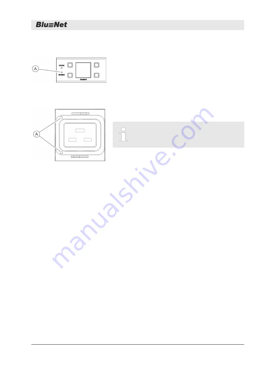
The Modbus LED displays the activity of the PDUs connected to
the Modbus.
If the connection between the master and slave PDU is lost, the
Modbus LED on the master PDU goes out and the Modbus LED on
the slave PDU flashes.
The status LEDs (only available on the BN3500/5000/7000/7500)
display the status of the loads connected to the sockets.
See the operating instructions for further information
about the status LEDs on the sockets.
1.4 Communication
A temperature sensor and a humidity sensor can be connected to
the PDU via the ports for sensors. The values can be called up
under
‘Status
è
External sensors’
in the web interface.
Several PDUs can be connected to each other via the Modbus
port. This way, up to 10 slave PDUs can be cascaded with a
master PDU and managed via the web interface. The slave PDU is
connected to the master PDU via the M1 Modbus port. Further
slave PDUs are connected to each other via the M1/M2 Modbus
ports of the particular slave PDU.
The PDU can be integrated into the network via the LAN port. The
data transfer rate is controlled via the network.
There is a USB port on the PDU next to the display and control
panel. This is for updating the firmware.
Modbus LED
Fig. 10: Modbus LED
Status LED on the sockets
(only on BN3500/5000/7000/7500)
Fig. 11: Status LEDs on the sockets
Connection for sensors S1/S2
M1/M2 port for Modbus
LAN port (10/100 Mbit/s)
USB port for firmware updates
(only on the master PDU)
Overview
Communication
25.09.2015
BlueNet PDU BN3000/3500/5000/7000/7500
11


