P. Bonding System Maintenance
The sacrificial zinc anodes on the hull, trim tabs, and
rudder (and prop shaft, if installed) should be
inspected periodically, replaced as necessary and
never painted. It is normal for the sacrificial zinc
anodes to appear “corroded” and decrease in size
over time.
A properly functioning bonding system will essentially
join all the metals. A broken or corroded connection
will break this bond and may result in accelerated
corrosion. Inspect the system with a multi-meter to
determine any differences in potential between
fittings or high resistance in the wiring or connections.
7.4 Fresh Water
A. Water
Tank
The roto-molded polyethylene water tanks (see
Fig_6.3-4) have a deck-fill plate located to starboard.
(see Fig_6.3-1) Each is vented through a flush SS
fitting in the side deck (port and starboard). The sides
and top panels of the water tank are somewhat
flexible, and can expand outward when the tank is
full. The tank is not designed to be pressurized.
Pressurization from overfilling can result in leaking.
(Fig_6.3-4)
Note:
The water tanks are connected through a hose
run on the aft engine room bulkhead. Fill tanks
slowly to allow each tank to fill equally. Filling
tanks too quickly will cause uneven tank load
which will affect the boats trim.
B. Water
Heater
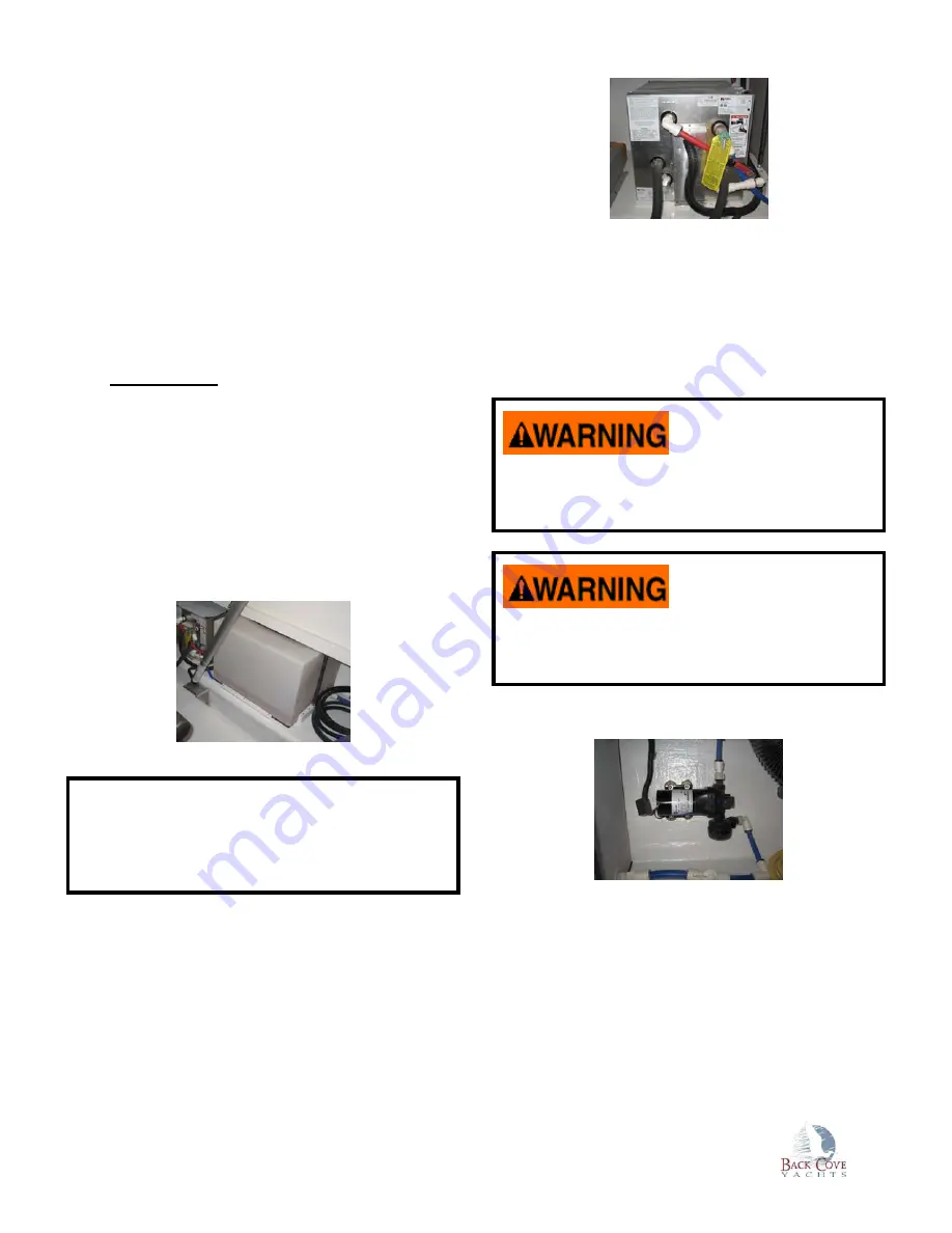
The water heater is located on the starboard side in
the engine room, forward of the water (starboard)
tank.
(Fig_6.3-2)
The water heater heats domestic fresh water with
either an electric heating element or by using engine
jacket water. (see Fig_6.3-2) The water heater must
be properly commissioned before use, as outlined in
the commissioning checklist. Refer to the
manufacturer's recommendations for additional
information.
The water heater must be filled with water before
switching “ON” the electric heating element.
Operating the water heater without water will
cause the electric heating element to fail.
Scalding may occur due to overheating the
domestic water after the engine has been run for
some time. Always exercise care when running
hot water.
C. Water
Pump
(Fig_6.3-3)
The Water pump is located on the starboard side of
the engine room, aft of the water (starboard) tank.
(see Fig_6.3-3)
The water pump is sized to assure adequate water
flow and have minimum surging as it cycles. When
the system senses a need for water the pump will
immediately start. Use of only one faucet at a time is
recommended.
Summary of Contents for Back Cove 30
Page 1: ...Back Cove 30 Owner s Manual...
Page 30: ...5 0 V e s s e l O v e r v i e w 5 1 General Arrangement Cockpit Helm Deck Cabin...
Page 35: ...5 3 Mechanical Overview Lazarette Engine Room Forward Bilge Zone...
Page 61: ...Fig_6 12c 7 Fig_6 12c 8 Companionway Fig_6 12c 9 Mate Seat Footrests Companionway Catch s...


