background image

1

2

3

4

5

6

7

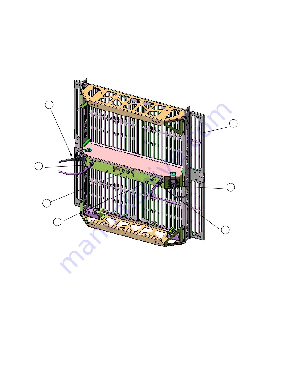
Winvision 1875 Panel Overview

Each Winvision 1875 panel provides  a 600 mm (15.69”) x 600mm wide screen of 
1024 LEDs with 18.75mm pixel pitch.  An array of panels can accomplish almost 
any form of desired user screen sizes and shapes.

1

Power Input 85~264 VAC, 50/60 Hz

2

Data Input

3

Data Output to Next Module (H)

4

Data Output to Next Module (V)

5

Power Output to Next Module

6

LED Display Panel (4 X 225 RGB SMD ) 

7

Video Address Writer & Status Indicator

Legend

Description

Summary of Contents for Winvision1875

Page 1: ...Winvision1875 User s Guide June 2008...

Page 2: ...75 Handling care 5 WinVision1875 2 Sub assembly 6 WinVision1875 Hanging Bracket 7 MCU WinVision1875 Main Control Unit 8 MCU Mode WinVision1875 Horizontal 9 Address Table WinVision1875 Horizontal 10 MC...

Page 3: ...m pixel pitch An array of panels can accomplish almost any form of desired user screen sizes and shapes 1 Power Input 85 264 VAC 50 60 Hz 2 Data Input 3 Data Output to Next Module H 4 Data Output to N...

Page 4: ...125mm Winvision1875 Mechanical Dimensions 600mm 600mm 630mm 2 Panel Front View Panel Side View...

Page 5: ...600mm The power supply unit is located in the middle of 1875 rear panel Power and video control signal to the LED panels is distributed from here The power and signal connections to adjacent panels a...

Page 6: ...ocks for vertical stacking are provided Caution To prevent the module from falling the lock should be extended completely from the spring latch Maximum Hanging Weight 90 0kg 15 modules Vertical Load 9...

Page 7: ...DATA connection Input 1 Output 2 same data Inter module Power connection Input 1 Output 1 1 2 1 2 3 Address Indicator Mode Select Buttons Function Mode Selector for manual address assignment Automati...

Page 8: ...Inter Module Data Cable Inter Module Power Cable Butterfly Fastener...

Page 9: ...olors Trillion 48bit LED Nichia RGB 950mcd Brightness 2 400cd m2 AC Power In 100 240V Power Max 280 Watt Panel Internal Power DC 5V Weight 6 7Kg Panel Module Color Black Transparency 50 Dimensions L 6...

Page 10: ...gned to be the lightest weight careful handling is required during assembly carrying of the module and disassembly 6 Upper Plate 5 Lower Plate 4 Power In 2 Holding Grip Female Hinge Male Hinge LED PCB...

Page 11: ...ible to stand the module alone care must be taken so the module does not to fall on the LED side Can be used for lifting or carrying 1 Upper Plate 2 Holding Grip 3 Hinge 4 Power In Out 5 Lower Plate f...

Page 12: ...LED panel sub assembly Maximum care is required when handling the LED panels Frame sub assembly Frame itself can be assembled separately Caution Disassembly should be done by 2 persons at front and r...

Page 13: ...anger for WinVision1875 should be used Use of parallel bar is recommended to maintain a parallel position Use of slider lock for vertical Hanging Max 15 modules 3 Do not let modules lie down unattende...

Page 14: ...page Slight movement is allowed however when hanging many modules it should be placed at outer position as possible Maximum Load 100kg 15modules Caution Screw A is required for hanging more than 8 mo...

Page 15: ...g of MCU MONITOR DVI In signal converted to analog signal output for MONITOR DVI IN Digital Video Input signal Input Signal DVI Control Signal RS 232C crossed cable Outer Dimension W 430mm H 87mm D 29...

Page 16: ......

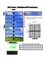
Page 17: ...110 120 130 140 150 16 MCU Mode WinVision1875 Horizontal 64pixel 544pixel 512pixel 1PORT can accommodate H 16 V 2 modules Individual output address mapping can be made using the provided software Addr...

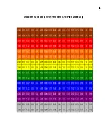
Page 18: ...Address Table WinVision1875 Horizontal 9...

Page 19: ...xel 8ports 1 0 32pixel 32pixel WinVision1875 Address Table Common to each PORT 0 00 0 02 0 03 0 01 0 04 0 05 0 06 0 07 0 08 0 09 0 10 0 11 0 12 0 13 1 00 1 02 1 03 1 01 1 04 1 05 1 06 1 07 1 08 1 09 1...

Page 20: ...Address Table WinVision1875 Vertical 1 1...

Page 21: ...Page SELECT COMPORT and System control A new PC or with multiple COM Port type in the port number to which RS232C cross cable would be connected win16pnp configuration Do not use it is configuration...

Page 22: ...are set System administrator only password required Default value is set at Brightness 100 Must set it to a value below 50 White Balance RGB sliders for white balance control are provided Brightness...

Page 23: ...ed Output Patch Port mapping 16 red numbers corresponds to MCU OUTPUT port 1 Select Output port Pressing a red number place X mark on itself 2 Port number patch Press a yellow number MCU Mode Selectio...

Reviews: