background image

/ / / / / / / / / / / / / / / / / / / / / / / / / / / / / / / / / / / / / / / / / / / / / / / / / / / / / / / / / / / / / / / / / / / / / / / / / / / / / / / / / / / / / / / / / / / / / / / / / / / / / / / / / / / / /

DA579 USER GUIDE 


FCC NOTICE                                                                                                 


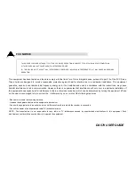
This equipment has been tested and found to comply with the limits for a Class B digital device, pursuant to part 15 of the FCC Rules. 
These limits are designed to provide reasonable protection against harmful interference in a residential installation. This equipment 
generates, uses and can radiate radio frequency energy and, if not installed and used in accordance with the instructions, may cause 
harmful interference to radio communication. However, there is no guarantee that interference will not occur in a particular installation. If 
this equipment does cause harmful interference to radio or television reception, which can be determined by turning the equipment off and 
on, the user is encouraged to try to correct the    interference by one or more of the following measures : 

 
- Reorient or relocate the receiving antenna. 
- Increase the separation between the equipment and receiver. 
- Connect the equipment into an outlet on a circuit difference from that to which the receiver is connected. 
- Consult the dealer of an experienced radio/TV technician for help. 
NOTE : The manufacturer is not responsible for any radio or TV interference caused by unauthorized modifications to this equipment. Such 
modifications could void the user's authority to operate the equipment. 


THIS DEVICE COMPLIES WITH PART 15 OF THE FCC RULES. OPERATION IS SUBJECT TO THE FOLLOWING TWO CONDITIONS: 

(1) THIS DEVICE MAY NOT CAUSE HARMFUL INTERFERENCE, AND 

(2) THIS DEVICE MUST ACCEPT ANY INTERFERENCE RECEIVED, INCLUDING INTERFERENCE THAT MAY CAUSE UNDERSIRED 

OPERATION.


Summary of Contents for DA579

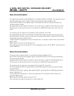
Page 1: ...2 4GHz DSS DIGITAL CORDLESS HEADSET MODEL DA579 USA VERSION BACKMI Corporation Circuit Explanation...

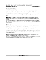
Page 2: ...to U1 and remixed with PN code and enerated Digital signal Digital signal is transformed into Analog at U1 This audio signal is passed through U42 T302 Configuration switch RL700 RL701 and transmitte...

Page 3: ...Q baseband signals are dc coupled to the ASIC U1 or U303 RXIP RXIN RXQP and RXQN inputs Transmit Path Base unit The baseband digital data input signal is shaped by external filter R919 C925 L901 C924...

Page 4: ...2 4GHz DSS DIGITAL CORDLESS HEADSET MODEL DA579 USA VERSION BACKMI Corporation User s Manual...

Page 5: ...DA579 USER GUIDE T T To o ot t ta a al lll lly y y W W Wi iir r re e el lle e es s ss s s D D DA A A5 5 57 7 79 9 9...

Page 6: ...ny 6 To reduce the risk of electric shock do not disassemble this product but take it to a qualified service contractor when some service or repair work is required Opening or removing covers may expo...

Page 7: ...ing the equipment off and on the user is encouraged to try to correct the interference by one or more of the following measures Reorient or relocate the receiving antenna Increase the separation betwe...

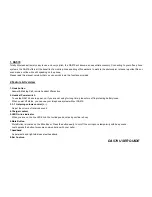
Page 8: ...PRECAUTIONS 1 Never install Headset wiring during a lightning storm 2 Never install headset jacks in wet locations unless the jack is specifically designed for wet locations 3 Use caution when install...

Page 9: ...fter Jack 26 Audio in Jack 27 Power adapter 28 Telephone cord 30 Recording cord Option 1 Hook On Off 2 Power On Off 3 RX Volume 3 1 RX Volume 5 LED On line indicator 4 Charger 7 Headband 8 Ear Cushion...

Page 10: ...ote handset lifter action 2 Headset Power switch To use the DA579 have to power on If you are not using for long time please turn off to protecting battery loose When power off status you can use your...

Page 11: ...mote from telephone and base unit with headset please push the page button on base by near person headset led indicator blink and make tone sound to notice incoming call 18 Audio button Normal positio...

Page 12: ...hone cord 29 Audio cord for computer option 30 Recording cord option 31 Lifter Out Of Range Detection If you use the Headset too far away from the Base set during a call the Headset will alert you wit...

Page 13: ...et jack 3 Connect a power adapter 25 to base unit adapter jack 22 and then connect to a power socket 4 Headset Power on 5 For battery charging place the headset on the base unit 6 when power on headse...

Page 14: ...t and LED indicator on headset do not light on please check the wiring connection and ensure power adapter is connected Checking for Optimal Sound 1 Adjustment of Configuration Please perform as follo...

Page 15: ...ur voice pertinent left the TX volume switch 3 Recording during the call Connect Recording Cord 30 optionally supplied between Record Jack 23 and your computer or exterior recorder You may need this r...

Page 16: ...ndset Making calls 1 Remove the headset from the base unit Push the hook button 1 online indicator will light on 2 lift the telephone s handset and listen for a dial tone in your headset 3 Dial the de...

Page 17: ...switch location 20 Callers has difficulties hearing me 1 Check the Mute button 2 Check the boom position Microphone is placed as close as possible to your mouth 3 Adjust the TX level 19 4 Out of rang...

Page 18: ...chase to an authorized Back mi dealer or Return product personally with proof of purchase directly to Back mi with following procedures 1 Contact Back mi for specific return and shipping instructions...

Page 19: ...sulted from improper or unreasonable use of maintenance accident improper packing or unauthorized tampering alteration or modification as determined solely by us This warranty is void if the label bea...

Reviews: