background image


1

  o

f


19


Owner’s Manual


Conley


10’ x 10’ Gazebo with Awning and Bar


Model Number: CON-1010-21


SKU Number: 272-1939


Note: This gazebo frame is designed to be used as a permanent fixture. Remove the main canopy 
and awning when not in use or during high winds, rain or snow.


Summary of Contents for CON-1010-21

Page 1: ...10 x 10 Gazebo with Awning and Bar Model Number CON 1010 21 SKU Number 272 1939 Note This gazebo frame is designed to be used as a permanent fixture Remove the main canopy and awning when not in use or during high winds rain or snow ...

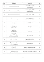
Page 2: ...tration Description Qty A Main Roof Connector 1 A1 Upper Roof Connector 1 A2 Upper Roof Support 4 A3 Finial 1 B Main Roof Corner Support 4 B1 Main Roof Corner Support Extension 4 C Main Roof Side Support 4 D Cross Beam 3 D1 Cross Beam 3 D2 Cross Beam 1 D3 Cross Beam 1 ...

Page 3: ...1 Corner Post 1 E2 Corner Post 1 F U Shaped Connector 8 F1 Cross Beam Corner Plate 4 G Cross Beam Center Connector Plate 4 H Bar Shelf 2 H1 Bar Support Stand 1 H2 Bar Connector 2 I Awning Frame Left Side 1 I1 Awning Frame Right Side 1 I2 Awning Corner Connector 2 ...

Page 4: ...k 2 J1 Awning Frame Right Front and Back 2 K Awning Frame Center 1 L Awning Hydrolic Rod 2 M Awning Lock 1 N Base Plate 4 O Base Cover 4 P Main Roof Canopy 1 P1 Upper Roof Vent Canopy 1 Q Awning Canopy 1 R M6 x 15 mm Bolt with Washer 112 S M6 x 32 mm Bolt with Nut and Washers 8 ...

Page 5: ...5 of 19 Letter Illustration Description Qty T M6 x 50 mm Bolt with Nut and Washers 2 U M6 x 15mm Bolt with Washer 8 V M6 Hex Wrench 2 W Allen Wrench 1 X Ground Stake 16 Y Accessory Hook 1 ...

Page 6: ...parts packed in the carton are present Note If any part is missing or damaged do not attempt to assemble Contact InSide Out Customer Support See page 19 Assemble on a stable level surface to avoid damage to gazebo and possible injury Two people are required to assemble this product Gazebo dimensions are measured from end of corner post base covers WARNING DO NOT TIGHTEN BOLTS UNTIL NOTED AFTER EAC...

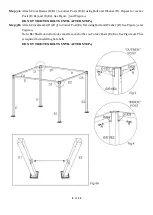
Page 7: ... Beam Center Connector Plate G into Cross Beam D D1 using Bolt and Washer R Repeat for remaining cross beams D D1 Insert Cross Beam Center Connector Plate G into Cross Beam D2 D3 using Bolt and Washer R See Figure 2 Tighten Bolts ...

Page 8: ...re 3 and Figure 4 DO NOT TIGHTEN BOLTS UNTIL AFTER STEP 4 Step 3B Attach Cross Beams D2 D3 to Corner Post E1 E2 using Bolt and Washer R See Figure 3 and Figure 4 Note Bar Shelf connector holes must face each other on Corner Posts E1 E2 See Figure 4A This is required for installing bar shelfs DO NOT TIGHTEN BOLTS UNTIL AFTER STEP 4 ...

Page 9: ...ts See Figure 5 1 Step 4B Connect the U Shaped Connector F to the center of the Cross Beams using Bolt and Washer U Repeat for three remaining Cross Beams See Figure 5 2 Step 4C Connect Cross Beam Corner Plates F1 across the top of the beams using Bolt and Washer R Repeat for each corner See Figure 6 TIGHTEN ALL BOLTS FROM STEP 3 AND STEP 4 ...

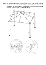
Page 10: ... Figure 7 Step 5B This step requires two people One person with the use of a ladder holds the Main Roof Connector A and the corner supports above the cross beams while the second person inserts one Main Roof Corner Support Extension B1 into a Main Roof Corner Support B and attaches it to the U Shaped Connector F on top of the Corner Posts using Bolt Nut and Washers S Repeat for three remaining ext...

Page 11: ...nector A until the push button lock clicks Attach the opposite end of the Main Roof Side Support C to the U Shaped Connector F in the center of the cross beam using Bolt Nut and Washers S Repeat for three remaining Side Supports C See Figure 9 and Figure 10 TIGHTEN BOLTS ...

Page 12: ...lt and Washer R See Figure 11 TIGHTEN BOLTS Step 8 Using two people connect one end of the Bar Shelf H to Bar Connector H2 using Bolt and Washer R Attach opposite end to the Bar Support Stand H1 using Bolt and Washer R Repeat for second Bar Shelf H See Figure 12 and Figure 13 TIGHTEN BOLTS ...

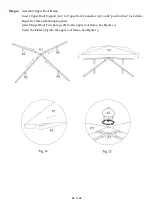
Page 13: ...rt Upper Roof Support A2 to Upper Roof Connector A1 until push button lock clicks Repeat for three remaining supports Attach Upper Roof Vent Canopy P1 to the upper roof frame See Figure 14 Screw the Finial A3 into the upper roof frame See Figure 15 ...

Page 14: ...e open corner seams are placed over Corner Posts E1 E2 Do not secure the Main Roof Canopy P until the upper roof frame is installed Step 10B Attach assembled upper roof frame by inserting the Upper Roof Support A2 into the Main Roof Corner Supports B until the push button lock clicks Repeat for each corner See Figure 16 ...

Page 15: ...Main Roof Canopy P to the four Main Roof Corner Support Extensions B1 See Figure 17 Step 11B Secure the Main Roof Canopy P to the four Main Roof Side Supports C See Figure 18 Note Canopy will be tight once secured to the roof frame ...

Page 16: ...ack Awning Frame J1 and the Center Awning Frame K with Bolts and Washers R Repeat for the front awning frame See Figure 20 and Figure 21 Step 12C Attach Awning Corner Connector I2 to Right Side Awning Frame I1 and Front Awning Frame J1 using Bolts and Washers R See Figure 22 Repeat for second Awning Corner Connector I2 to Left Side Awning Frame I and Front Awning Frame J using Bolts and Washers R ...

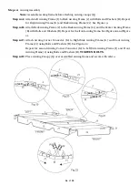
Page 17: ...f the Awning Hydrolic Rod L to Corner Post E1 and the opposite end to awning frame using Bolts and Washers R Repeat for second Hydrolic Rod L on Corner Post E2 See Figure 23 2 Step 13C Attach the Awning Lock M to Corner Posts E1 using Bolts and Washers R See Figure 24 1 TIGHTEN BOLTS Step 13D When awning is in the closed position use the Awning Lock M to secure awning to gazebo frame See Figure 24...

Page 18: ...p 14 Insert four Stakes X into the ground through the Base Plate N Repeat for each corner See Figure 25 Note Please see our video for additional assembly assistance https insideout store video assembly instructions ...

Page 19: ... EXCLUSIONS Gazebo use for commercial contract or other non residential purposes damage due to acts of nature vandalism misuse or improper assembly are not covered Discoloration or fading of the finish or fabrics as a result of chemicals or spills pool water chemicals or salt water is not covered Mildew of fabric is not covered Corrosion and rusting of frames and hardware is not covered If within ...

Reviews: