background image


4

  o

f


11


Assembly Instructions


10’ x 10’ Brunson Pergola


Note: For video instructions please visit:


https://insideout.store/video-assembly-instructions/


Important:


Read  all  the  instructions  before  assembly.  Failure  to  do  so  may  result  in  faulty  assembly  and 
potential injury.


Before assembling the product, remove all protective materials, hardware kit(s), and identify all 
parts packed in the carton are present. (Note: If any part is missing or damaged, do not attempt to 
assemble). Contact InSide Out Customer Support. See page 11.


Assemble on a stable level surface to avoid damage to gazebo and possible injury.


Two people are required to assemble this product.


Pergola dimensions are measured from end of corner post base covers.


WARNING: TIGHTEN BOLTS AFTER EACH STEP ONCE PARTS ARE ALIGNED!


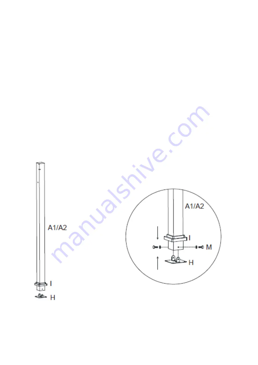
Step 1:


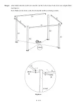
Insert Corner Posts (A1 & A2) into Base Cover (I). Attach Base Plate (H) to Corner Posts (A1 & A2) 
using Bolt (M). See Figure 1.


Figure 1


Summary of Contents for PERG-1111

Page 1: ...1 of 11 Owner s Manual 10 x 10 Brunson Pergola Model Number PERG 1111 SKU Number 272 1153 Note This pergola frame is designed to be used as a permanent fixture on level surface...

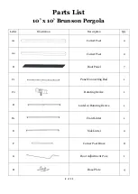
Page 2: ...Illustration Description Qty A1 Corner Post 2 A2 Corner Post 2 B Roof Panel 7 C1 Panel Connecting Rod 1 C2 Rotating Device 1 D Lintel w Rotating Device 1 D1 Front Lintel 1 E Side Lintel 2 F Corner Pos...

Page 3: ...4 J Roof Panel Connectors 13 K Rotating Device Connector 1 L Pull Down Screen 2 M M6 x 15mm Bolt with Washer 78 N M6 x 75mm Bolt with Washer 8 O M6 x 15mm Bolt 20 P Self Tapping Screw 4 Q M6 Open Wren...

Page 4: ...ntify all parts packed in the carton are present Note If any part is missing or damaged do not attempt to assemble Contact InSide Out Customer Support See page 11 Assemble on a stable level surface to...

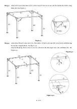
Page 5: ...5 of 11 Step 2 Attach Side Lintel E and Front Lintel D and D1 to the Corner Posts A1 A2 using Bolt M See Figure 2 Note Make sure the holes on the Front Lintel D and D1 are facing inwards Figure 2...

Page 6: ...sing Bolts M See Figure 3 Figure 3 Step 4 Attach Roof Panel Connectors J to the interior of the Front Lintel D1 and Lintel with Rotating Device D using Bolts O See Figure 4 1 Attached Rotating Device...

Page 7: ...middle hole of Lintel with Rotating Device D See Figure 5 Step 6 Attach Roof Panels B to the Roof Panel Connectors J using Bolts M See Figure 6 1 Attach Rotating Device Connector K to Roof Panel B us...

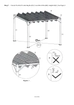
Page 8: ...8 of 11 Step 7 Connect the Panel Connecting Rod C1 to each Roof Panel B using Bolts O See Figure 7 Figure 7...

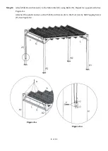
Page 9: ...ull Down Screen L to the Side Lintel E using Bolts N Repeat for opposite side See Figure 8 1 Attached the plastic anchor on the Pull Down Screen L to the Post A1 by Self Tapping Screw P See Figure 8 2...

Page 10: ...rner Posts A1 A2 See Figure 9 Insert the Stake T into the ground through Base Plate H to fix the gazebo See Figure 10 Note Please see our video for additional assembly assistance https insideout store...

Page 11: ...non residential purposes damage due to acts of nature vandalism misuse or improper assembly are not covered Discoloration or fading of the finish or fabrics as a result of chemicals or spills pool wat...

Reviews: