background image


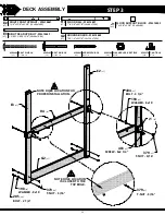
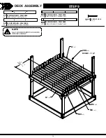
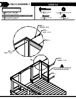
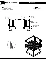
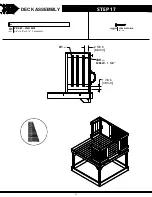
DECK ASSEMBLY

STEP 3

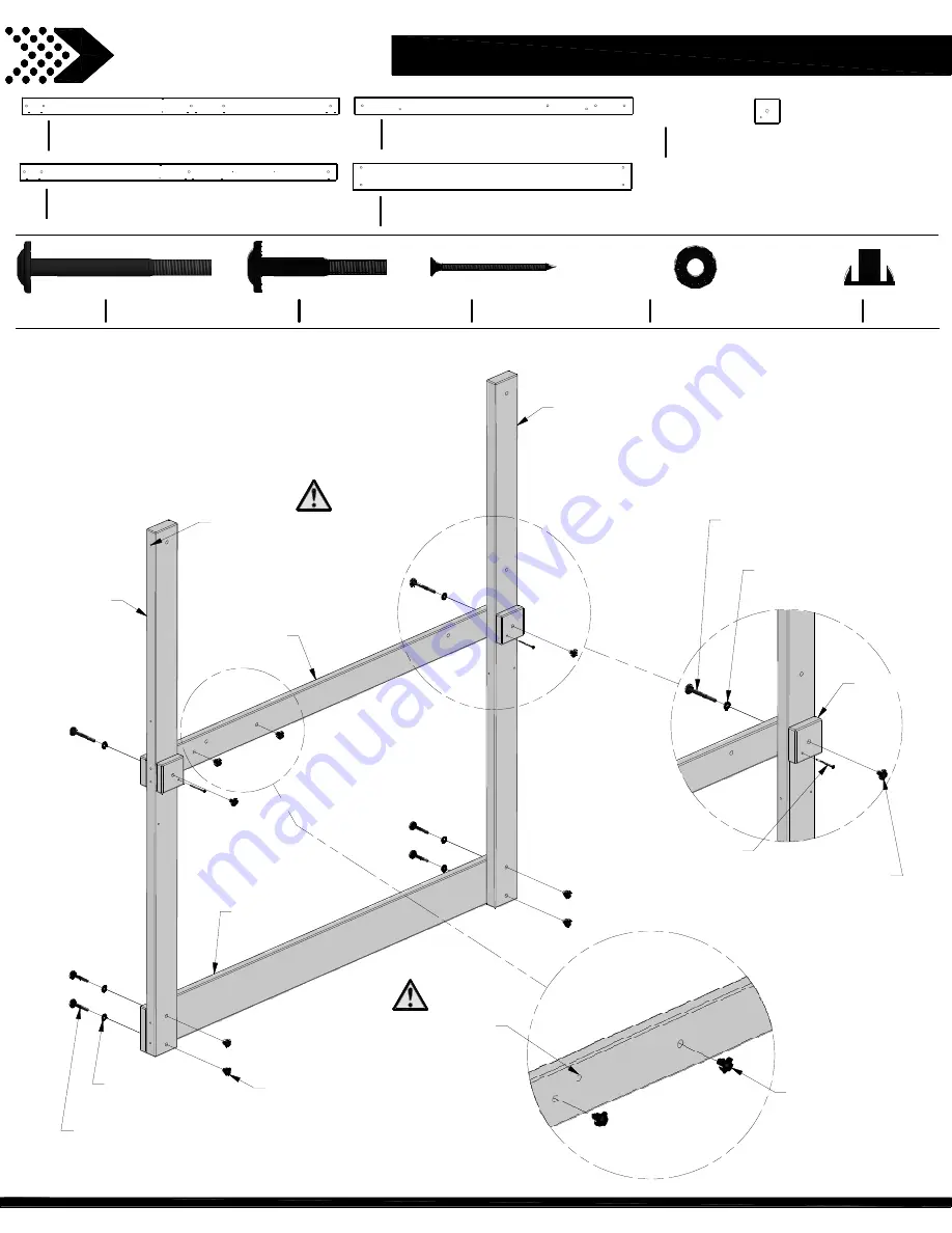
NOTE HOLE LOCATION FOR
PROPER INSTALLATION.

NOTE HOLE LOCATION

IS CLOSER TO THE

TOP EDGE.

484


(x2)

BOLT - 3 1/4"

198


(x2)

WASHER - 8x19

379


(x2)

T-NUT - 5/16"

483


(x2)

SCREW - 8x2 1/4"

379


(x2)

T-NUT - 5/16"

205


(x4)

BOLT - 2 1/4"

198


(x4)

WASHER - 8x19

379


(x4)

T-NUT - 5/16"

E2 

(x1)

E3 

(x1)

G2 

(x1)

J1 

(x2)

H4 

(x1)

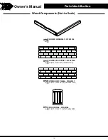
FLOOR RAIL - W4L14891

1"x3 3/8"x54 7/8" (24x86x1394)

H4

(x1)

RIGHT FRONT UPRIGHT - W4L14881

1 3/8"x3 3/8"x62 3/8" (36x86x1584)

E2

(x1)

RIGHT REAR UPRIGHT - W4L14882

1 3/8"x3 3/8"x62 3/8" (36x86x1584)

E3

(x1)

FLOOR SUPPORT BLOCK - W4L14902

1"x3 3/8"x3 3/8" (24x86x86)

J1

(x2)

GROUND BOARD - W4L14885

1"x5 1/4"x54 7/8" (24x134x1394)

G2

(x1)

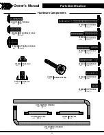
BOLT WH BLK

5/16x3 1/4

(x2)

H100484

BOLT WH BLK

5/16x2-1/4

(x4)

H100205

SCREW PFH BLK

 8x2 1/4

(x2)

H100483

WASHER LOCK EXT BLK

8x19

(x6)

H100198

T-NUT BLK

5/16

(x8)

H100379

33

Summary of Contents for 2102316

Page 1: ...ARTS Model 2102316 Echo Heights Owner s Manual Assembly Instructions MANUFACTURED BY Backyard Discovery 3305 Airport Drive Pittsburg KS 66762 800 856 4445 Basepoint Business Centre Rivermead Drive Westlea Swindon SN5 7EX average 2 person assembly time assembly time may vary based on skill level Playhouse WARNING Adult Assembly Required Not suitable for children under two years due to sharp points ...

Page 2: ...m for more info Installation services are only available to U S customers With Go Con gure we bring you 18 years of experience right to your doorstep We service a wide array of indoor and outdoor recreation products that most consumers don t have the time or ability to deliver install themselves We do the heavy lifting so you don t have to Installation services are only available to U S customers ...

Page 3: ...ead This Before Starting Assembly Owner sManual Read entire assembly manual paying special attention to the important tips and safety information Ensure there are no missing pieces by first separating and identifying all parts Make sure to check packing material for small parts that may have fallen out during shipment Structures are not intended for public use Any unintended use such as home child...

Page 4: ...ry will replace any parts within the rst 30 days from date of purchase found to be missing from or damaged in the original packaging This warranty applies to the original owner and registrant and is non transferable Regular maintenance is required to assure maximum life and performance of this product Failure by the owner to maintain the product according to the maintenance requirements may void t...

Page 5: ...ting shoes Loose clothing such as scarves and ponchos should not be worn Always take off tie up or tuck in cords and drawstrings on children s clothing These things can get caught on playground equipment and strangle a child Do not allow children to walk in front between behind or close to moving rides Instruct children not to attach items to the equipment that are not specifically designed for use ...

Page 6: ...g until after the unit is completely constructed Play house should not be built on top of surfacing Use containment such as digging out around the perimeter and or lining the perimeter with landscape edging Installations of rubber tiles or poured in place surfaces other than loose fill materials generally require a professional and are not do it yourself projects Shall use Playground Surfacing Mate...

Page 7: ...halt X3 1 4 Poured In Place Surfaces or Pre Manufactured Rubber Tiles You may be interested in using surfacing other than loose fill materials like rubber tiles or poured in place surfaces X3 1 4 1 Installations of these surfaces generally require a professional and are not do it yourself projects X3 1 4 2 Review surface specification before purchasing this type of surfacing Ask the installer manu...

Page 8: ... beginning of each season Inspect wood parts monthly The grain of the wood sometimes will lift in the dry season causing splinters to appear Light sand may be necessary to maintain a safe playing environment Treat your playset with stain regularly to help prevent severe checking splitting and other weather damage A waterborne transparent stain has been applied to your playset This is done for colo...

Page 9: ...nt will vary more widely than in thinner wood 2 Warping results from any distortion twisting cupping from the original plane of the board and often happens from rapid wetting and drying of the wood 3 Fading happens as a natural change in the wood color as it is exposed to sun light and will turn grey over time How can I reduce the amount of weathering to wood product 1 Your wood product is coated ...

Page 10: ...m the T Nut Turn clockwise to thread into T nut Do not completely tighten until instructed 7 187 LOCK WASHER BOLT Lag Assembly Normally there will be a pre drilled pilot hole on assemblies that require a Lag Screw If there is no pilot hole line up the two boards as they are to be attached and use the factory drilled hole as a guide to drill another pilot hole into the adjoining board This will kee...

Page 11: ...inless as possible Sorting Wood Sorting Hardware When removing the wood from the boxes we recommend arranging them by part number before you begin assembly This will allow for faster assembly and easily identify any parts that may be missing or damaged To help with assembly we recommend sorting your hardware bags with the seven digit alpha numeric number printed on the bags or by hardware type i e...

Page 12: ...wever there is no guarantee that interference will not occur in a particular installation If this equipment does cause harmful interference to radio or television reception which can be determined by turning the equipment off and on the user is encouraged to try to correct the interference by one or more of the following measures Reorient or relocate the receiving antenna Increase the separation b...

Page 13: ...Owner s Manual Tools Required for Installation 13 ...

Page 14: ...use Ground Dimension 6 25 ft 1 9 m x 10 02 ft 3 1 m Safe Play Area 19 42 ft 5 9 m x 23 19 ft 7 1 m x 14 18 ft 4 3 m SAFE PLAY AREA DIAGRAM Selecting the correct location for your play product is important for your children s safety and the product s longevity The safe play area refers to a zone extending 6 7 2m beyond the play product on all sides including the space above the play product Owner s...

Page 15: ...14889 1 x3 3 8 x54 7 8 24x86x1394 H2 x1 COUNTER TOP SUPPORT W4L14919 1 x3 3 8 x8 3 8 24x86x214 H3 x1 FLOOR RAIL W4L14891 1 x3 3 8 x54 7 8 24x86x1394 H4 x1 FLOOR RAIL W4L14888 1 x3 3 8 x56 3 4 24x86x1442 H1 x2 FLOOR SUPPORT W4L14892 1 x3 3 8 x54 7 8 24x86x1394 H5 x2 GROUND BOARD W4L14884 1 x5 1 4 x56 3 4 24x134x1442 G1 x2 GROUND BOARD W4L14885 1 x5 1 4 x54 7 8 24x134x1394 G2 x2 WALL RAIL W4L14893 1...

Page 16: ... 8 x54 3 8 16x112x1382 L2 x1 GROWTH BOARD W4L14908 5 8 x3 3 8 x60 1 4 16x86x1530 M1 x1 DECK BRACE W4L14898 1 x3 3 8 x13 24x86x330 H20 x8 LADDER RUNG W4L14899 1 x3 3 8 x18 1 8 24x86x460 H76 x3 LEFT UPRIGHT W4L14900 1 x3 3 8 x38 3 8 24x86x976 H79 x1 RIGHT UPRIGHT W4L14901 1 x3 3 8 x38 3 8 24x86x976 H80 x1 ATTACHMENT BOARD W4L14914 1 x3 3 8 x19 1 4 24x86x488 H110 x1 WALL RAIL W4L14896 1 x3 3 8 x16 5 ...

Page 17: ...SUPPORT W4L14913 5 8 x3 3 8 x19 1 4 16x86x488 M73 x1 SLIDE BRACE W4L13297 5 8 x3 3 8 x14 1 4 16x86x362 M77 x1 SLIDE BRACE W4L13298 5 8 x3 3 8 x14 1 4 16x86x362 M78 x1 WINDOW SHELF W4L14917 5 8 x2 3 8 x19 1 8 16x60x485 N2 x2 RAIL BOARD W4L14920 1 x1 x26 3 4 24x24x679 S1 x2 WINDOW TRIM W4L14921 1 x1 x21 1 2 24x24x545 S2 x2 WINDOW TRIM W4L14922 1 x1 x23 3 8 24x24x594 S3 x2 COUNTER TOP W4L14907 1 x4 3...

Page 18: ...GHT CORNER PANEL W2A03151 WP2 x1 REAR RIGHT CORNER PANEL W2A03154 WP3 x1 FRONT LEFT CORNER PANEL W2A03157 WP4 x1 REAR LEFT CORNER PANEL W2A03160 WP5 x1 REAR CENTER PANEL W2A03163 1 1 4 x18 7 8 x20 7 8 32x478x536 WP6 x1 LEFT CENTER PANEL W2A03164 1 1 4 x18 7 8 x20 7 8 32x478x536 18 ...

Page 19: ...Parts Identification WP8 x2 HEADER ASSEMBLY W2A03165 RP1 x2 LOWER ROOF PANEL W2A03166 1 3 8 x13 x44 7 8 35x329x1140 DP1 x1 DOOR PANEL W2A03168 1 1 8 x19 1 8 x11 3 8 27x486x288 RP2 x2 UPPER ROOF PANEL W2A03167 1 3 8 x12 3 4 x44 7 8 35x324x1140 19 ...

Page 20: ...4 x2 H100398 T NUT BLK 5 16 x42 H100379 SCREW SETTER x1 H100764 TORX WRENCH T 30 x2 H100114 TORX BIT T 40 x2 A100042 TORX BIT T 30 x2 H100147 TORX WRENCH T 40 x2 A100041 BOLT WH BLK 5 16x1 2 x11 H100396 BOLT WH BLK 5 16x1 x4 H100468 BOLT WH BLK 5 16x1 1 2 x7 H100407 BOLT WH BLK 5 16x1 3 4 x11 H100378 BOLT WH BLK 5 16x2 1 4 x15 H100205 BOLT WH BLK 5 16x3 1 4 x3 H100484 20 ...

Page 21: ...BLK 8x2 1 4 x3 H100483 SCREW PFH BLK 8x2 1 2 x33 H100201 SCREW PWH BLK 8x1 2 x9 H100408 SCREW PWH BLK 8x5 8 x13 H100202 SCREW PWH BLK 8x3 4 x11 H100392 SCREW PWH BLK 8x1 x7 H100797 SCREW POH BLK 8 32x1 1 8 x13 H100806 T NUT 8 32 x13 H100804 LAG SCREW WH BLK 5 16x2 x26 H100458 LAG SCREW WH BLK 1 4x1 1 2 x11 H100403 WASHER LOCK EXT BLK 8x19 x61 H100198 WASHER LOCK EXT BLK 12x19 x8 H100199 WASHER LOC...

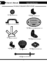
Page 22: ...1 A100314 90 L BRACKET BLK x8 A4M00555 HAND GRIP GREEN PLASTIC x2 A100028 BYD ID TAG MEDIUM AGES 2 TO 10 x1 A4M00528 L BRACKET 2 5x38x55x55 x3 A4M01047 PLASTIC SUNBURST x2 A100361 KNOB BLK x1 A6P00067 FAUCET KIT x1 A6P00024 SURFACE MOUNT BASIN x1 A6P00032 AUGER GROUND STAKE x4 A100178 22 ...

Page 23: ...ale Parts Identification HINGE DOOR SPRING LOADED x1 A4M00624 HINGE DOOR NON SPRING LOADED x1 A4M00994 DOOR STOP x1 A4M00933 6 FT SLIDE RAIL LEFT x1 A6P00389 6 FT SLIDE RAIL RIGHT x1 A6P00390 6 FT SLIDE BED x1 A6P00391 BELL ASSEMBLY x1 A4M01045 23 ...

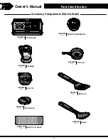
Page 24: ...to Scale Parts Identification BOIL POT x1 A6P00336 FRY PAN x1 A6P00338 POT PAN LID x2 A6P00337 SPATULA x1 A6P00339 LADLE x1 A6P00340 INDUCTIVE BURNER KIT x1 A6P00330 BLENDER x1 A6P00331 STOVE BASE x1 A6P00335 VERTICAL ID PLATE x1 A4M01150 24 ...

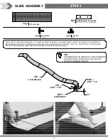
Page 25: ...ED USE A 3 8 DRILL BIT TO DRILL THE PILOT HOLES INTO THE SLIDE BED ATTACH THE SLIDE BED SUPPORT BOARD USING THE HARDWARE PROVIDED 391 x1 6 FT SLIDE BED 396 x2 BOLT 1 2 379 x2 T NUT 5 16 SLIDE ASSEMBLY M77 x1 SLIDE BRACE 6 FT SLIDE BED 1 A6P00391 1 2 SLIDE BRACE W4L13297 5 8 x3 3 8 x14 1 4 16x86x362 M77 1 PRE BENDING THE ENDS WILL EASE ASSEMBLY PLACING THE SLIDE BED OUT IN THE SUN MAKES IT EASIER T...

Page 26: ...PER BENDS THE SLIDE BED INTO THE CHANNEL MAKE SURE THE SLIDE BED IS COMPLETELY INSERTED INTO THE CHANNEL SEE VIEWING WINDOW BELOW 2 INSERT THE TWO CENTER SLIDE BRACES INTO THEIR RESPECTIVE LOCATIONS 3 USE A 1 8 DRILL BIT DRILL PILOT HOLES IN EACH INDENTATION ALONG EACH SIDE RAIL THERE SHOULD BE 12 INDENTIONS ON EACH RAIL BE SURE TO DRILL THOUGH THE SLIDE RAIL AND THE SLIDE BED THEN SECURE WITH THE...

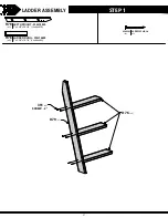
Page 27: ...LADDER ASSEMBLY STEP 1 LEFT UPRIGHT W4L14900 1 x3 3 8 x38 3 8 24x86x976 H79 x1 LADDER RUNG W4L14899 1 x3 3 8 x18 1 8 24x86x460 H76 x3 SCREW PFH BLK 8x2 x6 H100391 391 x6 SCREW 2 H76 x3 H79 x1 27 ...

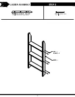
Page 28: ...LADDER ASSEMBLY STEP 2 SCREW PFH BLK 8x2 x6 H100391 RIGHT UPRIGHT W4L14901 1 x3 3 8 x38 3 8 24x86x976 H80 x1 391 x6 SCREW 2 H80 x1 28 ...

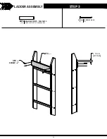
Page 29: ...LADDER ASSEMBLY STEP 3 SCREW PFH BLK 8x2 x4 H100391 REAR SUPPORT W4L14913 5 8 x3 3 8 x19 1 4 16x86x488 M73 x1 1 1 4 in 31 mm 391 x4 SCREW 2 M73 x1 29 ...

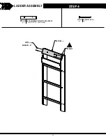
Page 30: ...LADDER ASSEMBLY STEP 4 SCREW PFH BLK 8x2 x4 H100391 ATTACHMENT BOARD W4L14914 1 x3 3 8 x19 1 4 24x86x488 H110 x1 FLUSH 391 x4 SCREW 2 H110 x1 30 ...

Page 31: ... 4 x5 H100205 T NUT BLK 5 16 x6 H100379 WASHER LOCK EXT BLK 8x19 x6 H100198 NOTE HOLE LOCATION CLOSER TO TOP EDGE NOTE HOLE LOCATION FOR PROPER INSTALLATION NOTE HOLE LOCATION FOR PROPER INSTALLATION NOTE HOLE LOCATION FOR PROPER INSTALLATION E1 x1 H2 x1 J1 x1 E4 x1 G2 x1 FLOOR SUPPORT BLOCK W4L14902 1 x3 3 8 x3 3 8 24x86x86 J1 x1 205 x4 BOLT 2 1 4 198 x4 WASHER 8x19 379 x4 T NUT 5 16 483 x1 SCREW...

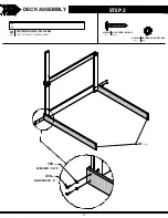
Page 32: ...DECK ASSEMBLY STEP 2 198 x4 WASHER 8x19 458 x4 LAG SCREW 2 G1 x2 GROUND BOARD W4L14884 1 x5 1 4 x56 3 4 24x134x1442 G1 x2 WASHER LOCK EXT BLK 8x19 x4 H100198 LAG SCREW WH BLK 5 16x2 x4 H100458 32 ...

Page 33: ... x2 H4 x1 FLOOR RAIL W4L14891 1 x3 3 8 x54 7 8 24x86x1394 H4 x1 RIGHT FRONT UPRIGHT W4L14881 1 3 8 x3 3 8 x62 3 8 36x86x1584 E2 x1 RIGHT REAR UPRIGHT W4L14882 1 3 8 x3 3 8 x62 3 8 36x86x1584 E3 x1 FLOOR SUPPORT BLOCK W4L14902 1 x3 3 8 x3 3 8 24x86x86 J1 x2 GROUND BOARD W4L14885 1 x5 1 4 x54 7 8 24x134x1394 G2 x1 BOLT WH BLK 5 16x3 1 4 x2 H100484 BOLT WH BLK 5 16x2 1 4 x4 H100205 SCREW PFH BLK 8x2 ...

Page 34: ...DECK ASSEMBLY STEP 4 LAG SCREW WH BLK 5 16x2 x4 H100458 WASHER LOCK EXT BLK 8x19 x4 H100198 198 x4 WASHER 8x19 458 x4 LAG SCREW 2 SUBASSEMBLY FROM STEP 3 34 ...

Page 35: ... 5 NOTE HOLE LOCATION IS CLOSER TO THE TOP EDGE LAG SCREW WH BLK 5 16x2 x4 H100458 FLOOR RAIL W4L14888 1 x3 3 8 x56 3 4 24x86x1442 H1 x1 WASHER LOCK EXT BLK 8x19 x4 H100198 198 x4 WASHER 8x19 458 x4 LAG SCREW 2 H1 x1 35 ...

Page 36: ... 6 FLOOR RAIL W4L14888 1 x3 3 8 x56 3 4 24x86x1442 H1 x1 LAG SCREW WH BLK 5 16x2 x4 H100458 WASHER LOCK EXT BLK 8x19 x4 H100198 NOTE HOLE LOCATION IS CLOSER TO THE TOP EDGE 198 x4 WASHER 8x19 458 x4 LAG SCREW 2 H1 x1 36 ...

Page 37: ...x19 403 x8 LAG SCREW 1 1 2 405 x8 WASHER 6x15 379 x8 T NUT 5 16 H20 x8 DECK BRACE W4L14898 1 x3 3 8 x13 24x86x330 H20 x8 BOLT WH BLK 5 16x1 3 4 x8 H100378 WASHER LOCK EXT BLK 8x19 x8 H100198 WASHER LOCK EXT BLK 6x15 x8 H100405 LAG SCREW WH BLK 1 4x1 1 2 x8 H100403 T NUT BLK 5 16 x8 H100379 37 ...

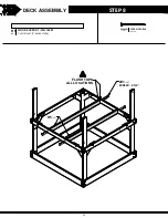
Page 38: ...DECK ASSEMBLY STEP 8 FLOOR SUPPORT W4L14892 1 x3 3 8 x54 7 8 24x86x1394 H5 x2 SCREW PFH BLK 8x2 1 2 x8 H100201 FLUSH TOPS ALL LOCATIONS H5 x2 201 x8 SCREW 2 1 2 38 ...

Page 39: ... x1 L1 x1 M6 x1 M4 x5 M4 x8 FLOOR BOARD W4L14909 5 8 x3 3 8 x56 3 4 16x86x1442 M4 x13 FLOOR BOARD W4L14905 5 8 x4 3 8 x54 3 8 16x112x1382 L2 x1 FLOOR BOARD W4L14904 5 8 x4 3 8 x52 16x112x1321 L1 x1 FLOOR BOARD W4L14886 5 8 x3 3 8 x56 3 4 16x86x1442 M6 x1 SCREW PFH BLK 8x1 1 2 x96 H100200 39 ...

Page 40: ... WALL RAIL W4L14895 1 x3 3 8 x34 1 4 24x86x871 H8 x1 WALL RAIL W4L14893 1 x3 3 8 x18 1 2 24x86x469 H6 x2 WALL RAIL W4L14894 1 x3 3 8 x56 3 4 24x86x1442 H7 x1 L BRACKET 2 5x38x55x55 x2 A4M01047 BOLT WH BLK 5 16x1 1 2 x4 H100407 T NUT BLK 5 16 x9 H100379 NUT BARREL WH BLK 5 16x5 8 x2 H100469 BOLT WH BLK 5 16x1 2 x4 H100396 BOLT WH BLK 5 16x2 1 4 x3 H100205 WASHER LOCK EXT BLK 8x19 x13 H100198 WASHER...

Page 41: ...x15 398 x2 T NUT 1 4 028 x2 HAND GRIP GREEN PLASTIC M10 x1 WALL BOARD W4L14911 5 8 x3 3 8 x26 1 2 16x86x673 M10 x1 L BRACKET 2 5x38x55x55 x1 A4M01047 HAND GRIP GREEN PLASTIC x2 A100028 WASHER LOCK EXT BLK 8x19 x2 H100198 WASHER LOCK EXT BLK 12x19 x1 H100199 BOLT WH BLK 5 16x1 1 2 x2 H100407 NUT BARREL WH BLK 5 16x5 8 x1 H100469 BOLT WH BLK 5 16x1 2 x2 H100396 T NUT BLK 5 16 x3 H100379 BOLT WH BLK ...

Page 42: ...8 x16 5 8 24x86x423 H9 x2 RAIL BOARD W4L14920 1 x1 x26 3 4 24x24x679 S1 x1 SCREW PFH BLK 8x1 1 2 x4 H100200 BOLT WH BLK 5 16x2 1 4 x2 H100205 WASHER LOCK EXT BLK 8x19 x2 H100198 T NUT BLK 5 16 x2 H100379 205 x2 BOLT 2 1 4 198 x2 WASHER 8x19 379 x2 T NUT 5 16 200 x4 SCREW 1 1 2 S1 x1 H9 x2 42 ...

Page 43: ... RAIL BOARD W4L14920 1 x1 x26 3 4 24x24x679 S1 x1 200 x4 SCREW 1 1 2 458 x2 LAG SCREW 2 198 x2 WASHER 8x19 SCREW PFH BLK 8x1 1 2 x4 H100200 NOTE HOLE LOCATION FOR PROPER INSTALLATION WASHER LOCK EXT BLK 8x19 x2 H100198 LAG SCREW WH BLK 5 16x2 x2 H100458 H10 x1 H10 x1 S1 x1 43 ...

Page 44: ...DECK ASSEMBLY STEP 14 PICKET W4L14918 5 8 x1 3 8 x20 1 2 16x34x520 O1 x3 1 7 8 in 49 mm SCREW PFH BLK 8x1 1 8 x6 H100380 380 x6 SCREW 1 1 8 O1 x3 2 1 8 in 54 mm PICKET PAL 44 ...

Page 45: ...DECK ASSEMBLY STEP 15 PICKET W4L14918 5 8 x1 3 8 x20 1 2 16x34x520 O1 x6 SCREW PFH BLK 8x1 1 8 x12 H100380 1 7 8 in 49 mm TYP 2 1 4 in 56 mm 2 1 4 in 56 mm 380 x12 SCREW 1 1 8 O1 x6 45 ...

Page 46: ...DECK ASSEMBLY STEP 16 PICKET W4L14918 5 8 x1 3 8 x20 1 2 16x34x520 O1 x7 SCREW PFH BLK 8x1 1 8 x14 H100380 2 1 4 in 58 mm 1 7 8 in 49 mm 380 x14 SCREW 1 1 8 O1 x7 46 ...

Page 47: ...DECK ASSEMBLY STEP 17 2 5 8 in 66 mm 1 7 8 in 49 mm PICKET W4L14918 5 8 x1 3 8 x20 1 2 16x34x520 O1 x3 SCREW PFH BLK 8x1 1 8 x6 H100380 380 x6 SCREW 1 1 8 O1 x3 47 ...

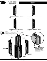
Page 48: ... FRONT RIGHT CORNER PANEL W2A03151 WP2 x1 REAR RIGHT CORNER PANEL W2A03154 WP4 x1 REAR LEFT CORNER PANEL W2A03160 WP3 x1 FRONT LEFT CORNER PANEL W2A03157 NOTE THE PROFILE OF THE WALL BOARDS THE TONGUE FACES TOWARD THE TOP OF THE PANELS LEFT BACK FRONT RIGHT WP3 x1 WP4 x1 WP2 x1 WP1 x1 48 ...

Page 49: ...PLAYHOUSE ASSEMBLY STEP 2 SCREW PFH BLK 8x1 x12 H100385 WP6 x1 LEFT CENTER PANEL W2A03164 1 1 4 x18 7 8 x20 7 8 32x478x536 385 x12 SCREW 1 WP6 x1 LEFT BACK FRONT RIGHT 49 ...

Page 50: ...PLAYHOUSE ASSEMBLY STEP 3 SCREW PFH BLK 8x1 x12 H100385 WP5 x1 REAR CENTER PANEL W2A03163 1 1 4 x18 7 8 x20 7 8 32x478x536 385 x12 SCREW 1 LEFT BACK FRONT RIGHT WP5 x1 50 ...

Page 51: ...PLAYHOUSE ASSEMBLY STEP 4 WP8 x2 HEADER ASSEMBLY W2A03165 SCREW PFH BLK 8x2 1 2 x4 H100201 ALL INTERIOR SURFACES ARE FLUSH LEFT BACK FRONT RIGHT WP8 x1 WP8 x1 201 x4 SCREW 2 1 2 51 ...

Page 52: ...4L14915 5 8 x3 3 8 x3 3 8 16x86x86 N1 x8 INSTALL WITH THE EDGE SURFACE OF N1 FLUSH WITH THE END OF WALL BOARD AS SHOWN 387 x32 SCREW 1 1 4 N1 x8 SCREW PFH BLK 8x1 1 4 x32 H100387 DRILL 1 8 3mm PILOT HOLE THIS HOLE ONLY THRU SIDING ONLY 52 ...

Page 53: ...x4 3 8 x25 3 8 16x112x644 L3 x4 BOLT WH BLK 1 4x1 x4 H100171 171 x4 BOLT 1 405 x4 WASHER 6x15 400 x4 WASHER 8x15 399 x4 NUT BARREL 7 8 L3 x4 WASHER LOCK EXT BLK 6x15 x4 H100405 WASHER LOCK EXT BLK 8x15 x4 H100400 NUT BARREL WH BLK 1 4x7 8 x4 H100399 53 ...

Page 54: ...PLAYHOUSE ASSEMBLY STEP 7 SCREW PWH BLK 8x3 4 x8 H100392 PLASTIC SUNBURST x2 A100361 SCREW PFH BLK 8x1 1 4 x4 H100387 361 x2 PLASTIC SUNBURST 392 x8 SCREW 3 4 387 x4 SCREW 1 1 4 54 ...

Page 55: ...PLAYHOUSE ASSEMBLY STEP 8 RP2 x1 RP2 x1 SCREW PFH BLK 8x1 1 2 x8 H100200 200 x8 SCREW 1 1 2 RP2 x2 UPPER ROOF PANEL W2A03167 1 3 8 x12 3 4 x44 7 8 35x324x1140 55 ...

Page 56: ...PLAYHOUSE ASSEMBLY STEP 9 SCREW PFH BLK 8x1 1 2 x8 H100200 200 x8 SCREW 1 1 2 RP1 x1 RP1 x1 RP1 x2 LOWER ROOF PANEL W2A03166 1 3 8 x13 x44 7 8 35x329x1140 56 ...

Page 57: ...PLAYHOUSE ASSEMBLY STEP 10 WINDOW SHELF W4L14917 5 8 x2 3 8 x19 1 8 16x60x485 N2 x1 FLUSH SURFACES N2 x1 387 x2 SCREW 1 1 4 SCREW PFH BLK 8x1 1 4 x2 H100387 57 ...

Page 58: ...PLAYHOUSE ASSEMBLY STEP 11 FLUSH SURFACES WINDOW SHELF W4L14917 5 8 x2 3 8 x19 1 8 16x60x485 N2 x1 SCREW PFH BLK 8x1 1 4 x2 H100387 N2 x1 387 x2 SCREW 1 1 4 58 ...

Page 59: ...PLAYHOUSE ASSEMBLY STEP 12 90 L BRACKET BLK x8 A4M00555 ALIGN BRACKETS WITH PILOT HOLES EDGES FLUSH IN DOOR OPENINGS SCREW PWH BLK 8x5 8 x8 H100202 202 x8 SCREW 5 8 555 x8 90 L BRACKET BLK 59 ...

Page 60: ...PLAYHOUSE ASSEMBLY STEP 13 H3 x1 200 x2 SCREW 1 1 2 COUNTER TOP SUPPORT W4L14919 1 x3 3 8 x8 3 8 24x86x214 H3 x1 SCREW PFH BLK 8x1 1 2 x2 H100200 ALIGN PILOT HOLES IN H3 WITH HOLES IN WALL PANEL 60 ...

Page 61: ...PLAYHOUSE ASSEMBLY STEP 14 COUNTER TOP SUPPORT W4L14903 1 x2 3 8 x9 1 4 24x60x234 J3 x2 387 x4 SCREW 1 1 4 1 8 in 2 mm J3 x2 LEFT RIGHT SIDE SCREW PFH BLK 8x1 1 4 x4 H100387 RIGHT LEFT 61 ...

Page 62: ...PLAYHOUSE ASSEMBLY STEP 15 COUNTER TOP W4L14907 1 x4 3 8 x36 3 4 24x112x934 Q1 x2 200 x10 SCREW 1 1 2 Q1 x2 9 32 in 7 mm SCREW PFH BLK 8x1 1 2 x10 H100200 62 ...

Page 63: ...PLAYHOUSE ASSEMBLY STEP 16 A REVISION TAG x1 A100314 392 x2 SCREW 3 4 314 x1 A REVISION TAG SCREW PWH BLK 8x3 4 x2 H100392 63 ...

Page 64: ...PLAYHOUSE ASSEMBLY STEP 17 1 1 2 in 37 mm FAUCET LOCATION 200 x2 SCREW 1 1 2 024 x1 FAUCET KIT FAUCET KIT x1 A6P00024 SCREW PFH BLK 8x1 1 2 x2 H100200 64 ...

Page 65: ...PLAYHOUSE ASSEMBLY STEP 18 SURFACE MOUNT BASIN x1 A6P00032 SCREW PWH BLK 8x5 8 x2 H100202 3 8 in 9 mm 202 x2 SCREW 5 8 032 x1 SURFACE MOUNT BASIN 65 ...

Page 66: ...SEMBLY STEP 19 WINDOW TRIM W4L14921 1 x1 x21 1 2 24x24x545 S2 x2 WINDOW TRIM W4L14922 1 x1 x23 3 8 24x24x594 S3 x2 S2 x2 S3 x2 387 x8 SCREW 1 1 4 SCREW PFH BLK 8x1 1 4 x8 H100387 9 3 4 in 247 mm 9 1 8 in 231 mm 66 ...

Page 67: ...ERIES OF THE SAME OR EQUIVALENT TYPE AS RECOMMENDED ARE TO BE USED BATTERIES ARE TO BE INSERTED WITH THE CORRECT POLARITY EXHAUSTED BATTERIES ARE TO BE REMOVED FROM THE TOY OR IF THE TOY IS TO BE LEFT UNUSED FOR A LONG TIME THE SUPPLY TERMINALS ARE NOT TO BE SHORT CIRCUITED RECHARGEABLE BATTERIES ARE TO BE REMOVED FROM THE TOY BEFORE BEING CHARGED RECHARGEABLE BATTERIES ARE ONLY TO BE CHARGED UNDE...

Page 68: ...PLAYHOUSE ASSEMBLY STEP 20 1 3 4 in 45 mm 335 x1 STOVE BASE STOVE BASE x1 A6P00335 797 x4 SCREW 1 SCREW PWH BLK 8x1 x4 H100797 68 ...

Page 69: ...PLAYHOUSE ASSEMBLY STEP 21 FASCIA BOARD W4L14912 5 8 x3 3 8 x25 5 8 16x86x652 M33 x2 387 x4 SCREW 1 1 4 M33 x2 SCREW PFH BLK 8x1 1 4 x4 H100387 69 ...

Page 70: ...PLAYHOUSE ASSEMBLY STEP 22 FASCIA BOARD W4L14912 5 8 x3 3 8 x25 5 8 16x86x652 M33 x2 SCREW PFH BLK 8x1 1 4 x4 H100387 387 x4 SCREW 1 1 4 M33 x2 70 ...

Page 71: ...ING LOADED x1 A4M00994 DOOR STOP x1 A4M00933 067 x1 KNOB BLK 933 x1 DOOR STOP 624 x1 HINGE DOOR SPRING LOADED 994 x1 HINGE DOOR NON SPRING LOADED 395 x2 SCREW 3 4 382 x1 SCREW 1 3 4 KNOB FASTENER 806 x6 SCREW 1 1 8 804 x6 T NUT 8 32 DP1 x1 SCREW POH BLK 8 32x1 1 8 x6 H100806 T NUT 8 32 x6 H100804 SCREW PFH BLK 8x3 4 x2 H100395 SCREW PFH BLK 8x1 3 4 x1 H100382 71 ...

Page 72: ...PLAYHOUSE ASSEMBLY STEP 24 806 x6 SCREW 1 1 8 804 x6 T NUT 8 32 DOOR SUBASSEMBLY x1 SCREW POH BLK 8 32x1 1 8 x6 H100806 T NUT 8 32 x6 H100804 72 ...

Page 73: ...PLAYHOUSE ASSEMBLY STEP 25 045 x1 BELL ASSEMBLY 797 x2 SCREW 1 BELL ASSEMBLY x1 A4M01045 SCREW PWH BLK 8x1 x2 H100797 73 ...

Page 74: ...FINAL ASSEMBLY STEP 1 378 x2 BOLT 1 3 4 198 x2 WASHER 8x19 WASHER LOCK EXT BLK 8x19 x2 H100198 BOLT WH BLK 5 16x1 3 4 x2 H100378 LADDER SUBASSEMBLY x1 74 ...

Page 75: ... BLK ASSEMBLED PREVIOUSLY SCREW PWH BLK 8x1 2 x8 H100408 382 x4 SCREW 1 3 4 PICKET MAY NEED TO BE TEMPORARILY REMOVED TO ASSEMBLE THE HOUSE TO THE DECK PICKET MAY NEED TO BE TEMPORARILY REMOVED TO ASSEMBLE THE HOUSE TO THE DECK 382 x4 SCREW 1 3 4 SCREW PFH BLK 8x1 3 4 x8 H100382 75 ...

Page 76: ...FINAL ASSEMBLY STEP 3 12 1 4 in 312 mm 202 x2 SCREW 5 8 528 x1 BYD ID TAG MEDIUM AGES 2 TO 10 BYD ID TAG MEDIUM AGES 2 TO 10 x1 A4M00528 SCREW PWH BLK 8x5 8 x2 H100202 76 ...

Page 77: ...FINAL ASSEMBLY STEP 4 GROWTH BOARD W4L14908 5 8 x3 3 8 x60 1 4 16x86x1530 M1 x1 SCREW PFH BLK 8x1 1 8 x4 H100380 3 1 8 in 80 mm M1 x1 380 x4 SCREW 1 1 8 77 ...

Page 78: ... STEP 5 1 in 25 mm 2 5 8 in 66 mm 7 1 8 in 180 mm 2 in 52 mm DRILLING LOCATIONS 3 5 in 89mm 396 x2 BOLT 1 2 379 x2 T NUT 5 16 6 FT SPEEDY SLIDE x1 9208032 BOLT WH BLK 5 16x1 2 x2 H100396 T NUT BLK 5 16 x2 H100379 78 ...

Page 79: ...ARDWARE FINAL ASSEMBLY 47 1 8 in 1197 mm 7 3 4 in 197 mm 2 3 8 in 60 mm AUGER GROUND STAKE x4 A100178 469 x4 NUT BARREL 5 8 199 x4 WASHER 12x19 468 x4 BOLT 1 178 x4 AUGER GROUND STAKE FRONT LEFT LEFT NUT BARREL WH BLK 5 16x5 8 x4 H100469 BOLT WH BLK 5 16x1 x4 H100468 WASHER LOCK EXT BLK 12x19 x4 H100199 PERFORM THE SAME ASSEMBLY PROCESS FOR THE RIGHT SIDE DRILLING LOCATIONS 79 ...

Page 80: ...STEP 7 NOTE FINAL ASSEMBLY VERTICAL ID PLATE x1 A4M01150 SCREW PPH WZ 4x1 2 x4 H100360 360 x4 SCREW 4x1 2 WZ 150 x1 VERTICAL ID PLATE 1 2 in 12mm CENTER ID PLATE ON UPRIGHT 80 ...

Reviews: