background image

 7

ASSEMBLY INSTRUCTIONS

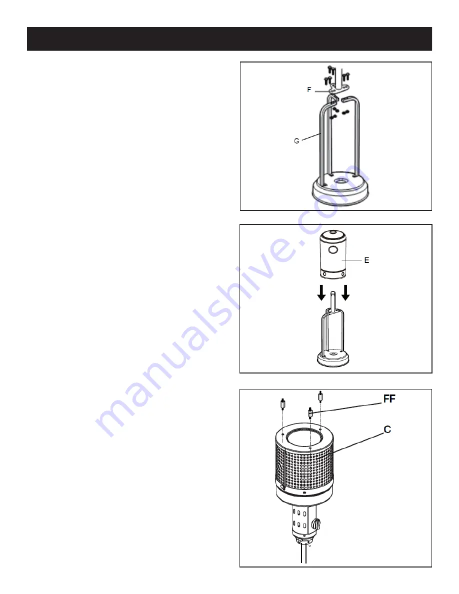
4. 

Attach the post support (F) to the top of the 

support legs (G) using 6 pcs M6 x 22 bolts (DD) 

and 6 pcs M6 nuts (BB).

5. 

Place the tank housing (E) on top of the 

assembly.

6. 

Screw the threaded end of the reflector studs 

(FF) into the top holes of the head assembly (C).

Summary of Contents for 554PH1BLK

Page 1: ...stallation adjustment alteration service or maintenance can cause injury or property damage Read the owner s manual thoroughly before installing or servicing this equipment If the information in this...

Page 2: ...to avoid burning skin or clothing Do not sit or rest hands or feet on this heating unit Never place hands or fingers on upper portion of this unit while in use Keep all electrical cords and fuel suppl...

Page 3: ...at least annually by a qualified service person More frequent cleaning may be required as necessary It is imperative that the control compartment burners and circulating airways of the appliance are k...

Page 4: ...Anchoring Arm 3 JJ Anchoring Nut 3 KK Cap Nut 9 LL Small screw 9 MM Webbing 1 Before beginning assembly of product make sure all parts are present Compare parts with package contents list and hardwar...

Page 5: ...5 CONTENTS ITEM DESCRIPTION QTY A Re ector Panel 3 B Center Re ector 1 C Head Assembly 1 D Post 1 E Tank Housing 1 F Post Support 1 G Support Legs 1 H Regulator 1 I Base 1 J Wheel Assembly 1...

Page 6: ...and 2 pcs M6 nuts BB 2 Mount the 3 pcs anchoring arms II to the holes on the base I using 6 pcs M6x10 screws AA and 6 pcs M6 nuts BB Optional If you wish the patio heater can be fixed by hammering the...

Page 7: ...st support F to the top of the support legs G using 6 pcs M6 x 22 bolts DD and 6 pcs M6 nuts BB 5 Place the tank housing E on top of the assembly 6 Screw the threaded end of the reflector studs FF int...

Page 8: ...ic protective coating on reflector panel A and center reflector B before assembling WARNING 8 Attach the reflector assembly made in step 7 to the top of the reflector studs FF on the head assembly C F...

Page 9: ...4 screws 11 Place the 20 lb gas cylinder in the center of the base fasten it with the webbing MM 12 Turn the cylinder valve on the tank clockwise to close the propane tank Attach the regulator H to th...

Page 10: ...ft cloth Harsh weather conditions may cause stubborn stains discoloration and possibly rust pitting Permanent damage may occur if powder or solvent comes in contact with painted or plastic components...

Page 11: ...after the ignition 5 If a new tank has just been connected allow at least one minute or more for the air in the gas pipeline to purge out 6 The flame can be watched and checked from the viewing hole l...

Page 12: ...with compressed air The burner flame is low The supply hose is bent or twisted Straighten the hose and perform a leak test There is blockage in the burner injector Clean or replace the burner injector...

Page 13: ...he control knob is in the OFF position There is a gas leak Locate and correct the leak immediately The gas control is defective Replace the gas control There is a gas odor during combustion There is f...

Page 14: ...plate has been removed or altered Damage or failure due to improper installation improper utility connection or supply and issues resulting from improper ventilation or airflow Defects and damage due...

Reviews: