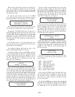
SENSOR CABLE CONNECTION
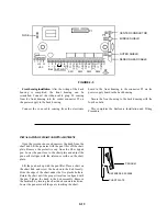
To wire the sensor head cable, the front half of the
Model 2100 enclosure, mounted in the back of the Model
2100R+ housing, must be removed. Use the 5/32 inch
Allen wrench supplied in the mounting hardware package
to loosen and remove all four hex bolts in the front of the
housing (see Figure 2-3). Separate the front and back
housings.
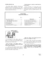
CAUTION: THERE IS A COAX SIGNAL WIRE
AND A RIBBON CABLE CONNECTED FROM THE
POWER SUPPLY BOARD TO THE FRONT HOUSING
THAT MUST BE DISCONNECTED WHEN REMOVING
THE FRONT HOUSING.
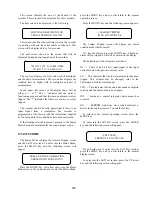
Place the front housing in a pro-
tected area so it will not be damaged. Figure 2-4 shows
the back housing with the power circuit board and
terminal connections. As mentioned before, the AC input
power has been wired from the factory. The sensor cable
connections are on the right side of the circuit board.
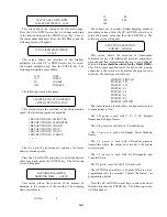
The cable for the sensor should be run in a separate
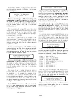
metallic conduit. Refer to Figure 2-2 and prepare the
cable ends in the following manner.
2-1/2"
2"
1-1/4"
3/4"
5/8"
5/8"
1/2"
3/4"
1/2"
1/8"
Remove
outer
cover
Remove
outer
shield
Remove
middle
cover
Remove
middle
shield
Remove
inner
cover
Completed
cable
1
2
3
4
5
6
FIGURE 2-2
1. Remove outer cable cover. Measure 2-1/2" from the
end of the cable. With a cutting tool, carefully cut through
the outer covering completely around the cable making sure
not to cut into the outer shield. Make another cut from the
first cut to the end of the cable and remove the outer cover.
2. Remove outer shield. Measure 2" from the end of
the cable. With a pair of small wire cutters, cut the shield
around the cable at the measured point and remove the cut
off shield.
3. Remove middle cover. Measure 1-1/4" from the end
of the cable. With a cutting tool, carefully cut through the
middle covering completely around the cable making sure
not to cut into the middle shield. Make another cut from the
first cut to the end of the cable and remove the middle
cover.
4. Remove middle shield. Measure 3/4" from the end
of the cable. With a pair of small wire cutters, cut the
shield around the cable at the measured point and remove
the cut off shield.
5. Remove inner cover. Measure 5/8" from the end of
the cable. With a cutting tool, or pair of wire strippers,
carefully cut the inner covering completely around the
cable, making sure not to cut into the center conductor
and remove the inner cover.
After the ends of the cables have been prepared, loosen
the screws on the terminal for the center conductor.
Remove the two cable clamps. Insert the center conductor
of the sensor cable into the center conductor terminal and
tighten the screw. Slightly pull on the cable to ensure the
wire is secured to the terminal.
Place the two pairs of clamps over the middle and outer
shields and secure them into place. Verify that the clamps
are making good contact with the shields and that no
wires of the shields are extending beyond their own
clamp down area.
2-10

