ERROR SCREENS
There are several Error Screens that will be displayed
by the recorder if the microprocessor detects errors in the
alues programmed into the recorder.
v
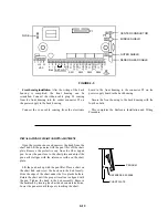
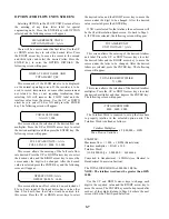
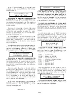
- CHART PEN ZERO -
<INPUT ZERO ERROR>
OR
- CHART PEN SPAN -
<INPUT SPAN ERROR>
If either of the two above Error Screens appears during
the chart pen adjusting procedure, one of the following
problems probably occurred.
1. There was not a 4-20 mADC analog signal to the
recorder analog channel you selected while adjusting the
chart zero or span.
2. An analog input signal channel was selected
without adjusting the chart pen zero and span of this
channel.
3. The Zero and Span of the recorder have been
adjusted too close to the same input value.
To correct these errors, readjust the chart pen zero and
span. Refer to Page 3-5 for the proper procedure.
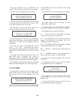
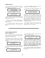
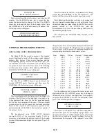
- STORING PARAMETERS -
<TOTALIZER WORD ERROR>
If the above Error Screen appears after pressing the
ENTER key to store the calibration adjustments, this
indicates that you have selected a totalizer multiplier that
is too low for your selected flow rate. To correct this
error, re-enter the Calibration Mode and when the
Totalizer Multiplier Screen appears, increase the totalizer
multiplier and press the ENTER key. Then press the
MENU key to store the new multiplier and return to the
normal operating screen.
If you still have a Totalizer Word Error message in the
Storing Parameters Screen, then repeat the above
procedure until the error is not present.
FLOW METER OPERATION
INITIAL POWER UP
After installation and wiring of the Model 2100R+,
power may be turned on by the power switch on the lower
right hand corner of the chart plate.
When power is applied, the display screen of the Model
2100 flow meter will have a solid line across the top of
the display for a few seconds. Then the following screen
will appear:
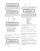
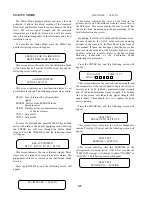
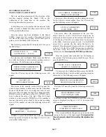
- BADGER METER -
SOFTWARE REV. - X.XX
This will be displayed for about 3 seconds and then the
next screen will show the serial number of the unit as
shown below.
- BADGER METER -
SERIAL NUMBER XXXXXXXX
This will be displayed for about 3 seconds and then the
following screen will be displayed:
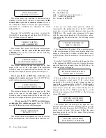
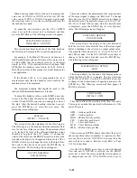
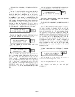
- FLOW 1234 X 10 GPM
FLUID LEVEL = 99.99 IN
This screen is considered the normal operating screen.
In the upper left corner of the display there will be either
a flashing '-' or '*'. The '-' indicates that the meter is
functioning properly and that there are no alarms or relays
tripped. The '*' indicates that there are alarms or relays
tripped.
If an 'F' appears, this indicates that the meter is
performing an auto frequency tuning procedure and the
MENU key will not respond until the 'F' goes away.
The following two sections describe the operation of
the Status and Calibration Modes of the Model 2100 flow
meter portion.
3-8


