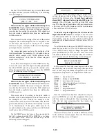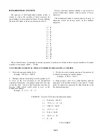
When selecting inches (IN) as the unit of measure, the
value can be XX.XX or XXX.X and for feet (FT) the
value can be X.XXX or XX.XX. You must step through
the selections twice to view the two different choices for
the inch and feet units.
To make the unit selection, use the UP or DOWN
arrow keys until the correct unit is displayed and then
press the ENTER key. The following screen will appear:
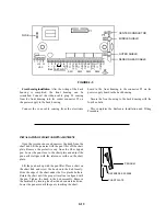
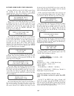
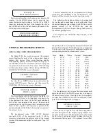
SELECTED FULLSCALE
HEAD RISE = XX.XX IN
This sets the maximum head rise of the fluid based on
the full scale to be measured for a specific application.
For example, if the Model 2100 was to be used on a 6
inch Parshall flume and the full scale of the meter was to
be 1000 GPM, then the headrise value set in the meter
would be 12.61. If the desired full scale had been 1800
GPM, then the headrise value would be 18.29. Refer to
Data Sheet in front of this manual for actual headrise for
your application.
If the Model 2100 is to be programmed for level
measurement only, then the headrise value would be the
maximum level to be measured.
The maximum headrise that should be used is 120
inches and the minimum headrise is 4 inches.
To adjust the headrise value, use the RIGHT arrow key
to move the line under the digit to be adjusted and then
use the UP and DOWN arrow keys to change the value of
the digit. After the desired headrise value has been set,
press the ENTER key to store this new value. The
following screen will appear:
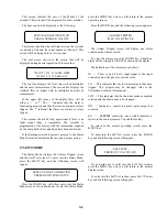
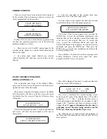
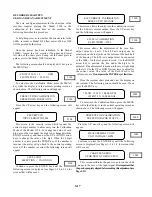
SENSOR
OFFSET = XXX.X IN.
This screen allows the adjustment of the offset region.
The offset region is the distance from the maximum fluid
level to the face of the sensor head. The minimum offset
is 12 inches. The total of the offset and headrise values
should not be greater than 132 inches. To change the
value of the offset, use the RIGHT arrow key to move the
line under the digit to be changed and then use the UP or
DOWN arrow keys to change the value of the digit. Once
the correct value has been set press the ENTER key to
store this value. The following screen will appear:
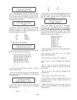
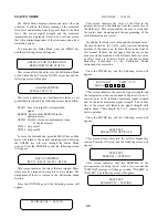
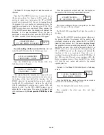
OUTPUT DAMPING
XXX SECONDS
This screen allows the adjustment of the response time
of the output signal to change sin fluid level. To change
this value, use the UP or DOWN arrow keys to change to
the desired value. The available values are 8, 126, 32, 64,
128, 256, 512 and 1024 seconds. Once the desired value
is displayed, press the ENTER key to store this new
value. The following screen will appear:
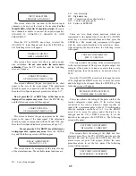
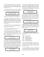
LOST ECHO DEFAULT
XXX SECONDS
This screen allows the setting of the time desired to
hold the last level value after the loss of the return signal
before defaulting to the selected no signal output value.
The available time values are 8, 16, 32, 64, 128, 256, 512
and 1024 seconds. Use the UP or DOWN arrow keys to
change to the desired value and press the ENTER key.
The following screen will appear:
METER DISPLAY OPTION
FLOW
This screen allows the selection of the display mode in
which the Model 2100 is to operate. The two selections
are FLOW or LEVEL. Use the UP or DOWN arrow key
to change to the desired mode of operation and press the
ENTER key. The following screen will then appear if
FLOW is selected:
FLOW LABEL
INITIALS = GPM
This screen allows the selection of the flow rate units.
There are seven units that are stored in the memory of the
meter. These are:
GPM - Gallons per Minute
GPD - Gallons per Day
MGD - Million Gallons per Day
CFS - Cubic Feet per Second
L/S
- Liters per Second
M3H - Cubic Meters per Hour
MLD - Million Liters per Day
There is also an OPTION choice that allows the user to
choose any three letters or numbers to represent the flow
rate unit that is desired. If OPTION is chosen, then the
user will have to input a totalizer word. Refer to Page
3-16 for instructions.
Use the UP or DOWN arrow keys to select the desired
flow rate unit. If OPTION is selected, use the RIGHT
arrow key to move the cursor under the letter position to
be changed and use the UP or DOWN arrow keys to
3-11


