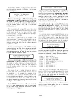
Use the UP or DOWN arrow keys to select the desired
multiplier and then press the ENTER key. The following
screen will appear:
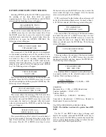
CONTACT INTEGRATOR
0000 X 1,000 GAL
This screen does not appear with the standard setup of the
Model 2100R+.
If at the TOTALIZER FUNCTION screen
the totalizer is enabled, this screen will appear. Since the
recorder has the totalizer function, the 2100 should not
have the totalizer enabled unless there is a malfunction
with the recorder.
This screen allows the setting of the rate of the contact
integrator. The contact integrator can be assigned to one
of the relays and be used as an output for a remote
totalizer or to pace a sampler or other devices requiring a
pulse input based on total flow.
The contact integrator can be set for multiples of the
totalizer multiplier. For example, if it is desired to have a
sampler take a sample every 10,000 gallons and the
totalizer multiplier is 1,000, then the contact integrator
would be set to 0010.
To set the contact integrator, use the RIGHT arrow key
to move the cursor under the digit to be changed and then
the UP or DOWN arrow keys to select the desired value.
After the desired value has been set, press the ENTER
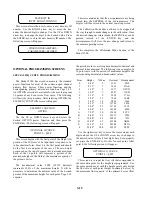
ey. The following screen will appear:
k
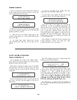
INTEGRATOR PULSE WIDTH
ON FOR 0002 X .0655 SEC.
This screen does not appear with the standard setup of the
Model 2100R+.
If at the TOTALIZER FUNCTION screen
the totalizer is enabled, this screen will appear. Since the
recorder has the totalizer function, the 2100 should not
have the totalizer enabled unless there is a malfunction
with the recorder.
This screen allows the setting of the pulse width or
duration of the contact integrator. The on time can be set
for multiplies of .0655 seconds. For example, if the
contact closure must be at least 100 milliseconds, then the
pulse width must be set for 0002 which would give a time
of 131 milliseconds. If the pulse width must be 30
seconds in duration, the value would be set at 0459 which
would give a time of 30.06 seconds.
Use the RIGHT arrow key to move the cursor under the
digit to be changed and the UP or DOWN key to change
to the desired value. Press the ENTER key and the
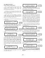
following screen will appear:
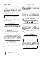
SETPOINT# 01
ON AT XX% OFF AT XX%
This screen allows the setting of the set points for low
or high alarms and the dead band. These values are in
percent of the full scale value.
To make the set point a low
alarm, the ON value must be lower than the OFF value.
For
example, if the ON value was 30% and the OFF value
was 35% then this set point alarm will be activated below
a flow rate of 30% of full scale and will be deactivated at
a flow rate above 35% of full scale.
To make the set point a high alarm, the ON value must be
higher than the OFF value.
For example, if the ON value
was 60% and the OFF value was 50%, then this set point
alarm will be activated at a flow rate above 60% of full
scale and will be deactivated at a flow rate below 50% of
full scale.
To set the desired values, use the RIGHT arrow key to
move the line under the ON or OFF values and use the
UP or DOWN arrow keys to change the values. Then
press the ENTER key to store the new values. The screen
will advance to the second set point. After the second set
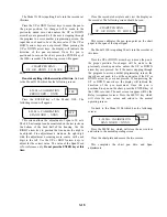
point has been entered, the following screen will appear:
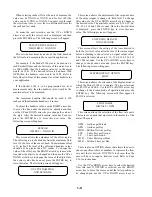
RELAY ASSIGNMENT
RELAY 01 => ECHO
In this screen the four relays are assigned to the alarm
on which they are to activate. Any relays that have been
used in the Pump Alternation assignments will not be
displayed for assignment. The assignments available are:
ECHO = Lost return echo
EEPRM = Failure of the EEPROM
OVRR = Level above the set span
4-20
= 4-20 mA output loop circuit open
CINT = Contact
Integrator
TOTL = Totalizer
PNT#2 = Set point number 2
PNT#1 = Set point number 1
Once the desired alarm has been selected for relay #1,
press the ENTER key to store this assignment. The screen
will then advance through the three remaining relays.
After the last relay assignment has been made, the
ollowing screen will appear:
f
4-20 CURRENT CALIBRATION
PRESS UP TO CHANGE
This screen allows the entry into the calibration screens
for the 4-20 mA current output. Press the UP arrow key
and the following screen will appear:
3-13


