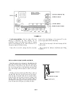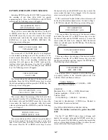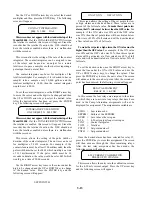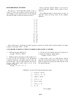
4-20 M.A CALIBRATION
ZERO WORD = XXXX
3-14
This screen allows the adjustment of the zero output to
4 mA. The 4-20 mA output can be monitored on the test
jacks on the bottom of the back half of the housing.
The 4-
20 mA output must be connected to a load for the test points to
work.
Use the RIGHT arrow key to position the line under
the digit to be adjusted. Fine adjustment is made on the
right digit with the adjustment becoming more coarse
with each digit to the left. Use the UP or DOWN arrow
keys to adjust for the correct value. The value of the Zero
Word is for reference only. Press the ENTER key to store
the value. The following screen will appear:
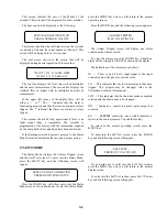
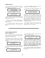
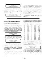
4-20 M.A CALIBRATION
SPAN WORD = XXXX
This screen allows the adjustment of span to 20 mA.
The 4-20 mA output can be monitored on the test jacks on
the bottom of the back half of the housing. Use the
RIGHT arrow key to position the line under the digit to
be adjusted. Fine adjustment is made on the right digit
with the adjustment becoming more coarse with each
digit to the left. Use the UP or DOWN arrow keys to
adjust for the correct value. The value of the Span Word
is for reference only. Press the ENTER key to store the
value. The following screen will appear:
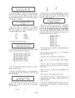
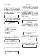
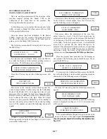
4-20 M.A CALIBRATION
DEFAULT WORD = XXXX
This screen allows the setting of the 4-20 mA output
signal when the meter goes into a default condition due to
the loss of a return signal. This value is set depending on
the user's desire for the value of the output to indicate a
default condition. The 4-20 mA output can be monitored
on the test jacks on the bottom of the back half of the
housing. Use the RIGHT arrow key to position the line
under the digit to be adjusted. Fine adjustment is made on
the right digit with the adjustment becoming more coarse
with each digit to me left. Use the UP or DOWN arrow
keys to adjust for the correct value. Press the ENTER key
o store the value. The following screen will appear:
t
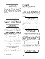
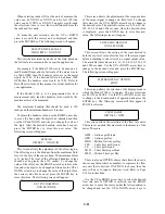
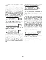
DISTANCE CALIBRATION
PRESS UP TO CHANGE
This screen allows entry into the distance calibration
screen which enables the calibration of the transmitter if
necessary. This is set at the factory and only needs to be
checked every three months. Do not set the distance
calibration to an arbitrary number. The display shows the
actual distance from the sensor to the surface at that
meas-
urement cycle. Checking will require measuring from the
bottom of the sensor (face) to the water, then setting
distance calibration to this measurement. Press the UP
arrow key and the following screen will appear:
DISTANCE CALIBRATION
NEAR DIST. => XX.XX IN
This screen calibrates the meter for the maximum flow
level. If this adjustment is made, the fluid surface should
be smooth to assure a steady reading. The near distance
calibration should be made during high flow - surface of
fluid at, or close to, the maximum (full scale) level.
Do not
perform this calibration if the distance from the sensor to the
surface is greater than 48 inches.
The display shows the
distance from the surface of the fluid to the sensor.
Checking will require measuring from the bottom of the
sensor (face) to the surface of the fluid and adjusting the
distance calibration to this measurement. Use the UP or
DOWN arrow keys to adjust to the correct value. Allow
time for the meter to settle. Press the RIGHT arrow key.
The following screen will appear:
DISTANCE CALIBRATION
FAR DIST. => XX.X IN.
This screen calibrates the meter for the zero flow level.
If this adjustment is made, the fluid surface should be
smooth to assure a steady reading. The far distance
calibration should be made during low flow - surface of
fluid at, or close to, the minimum (zero) level.
Do not
perform this calibration if the distance from the sensor to the
surface is less than 72 inches.
The display shows the distance
from the surface of the fluid to the sensor.
Checking will require measuring from the bottom of the
sensor (face) to the surface of the fluid and adjusting the
distance calibration to this measurement. Use the UP or
DOWN arrow keys to adjust to the correct value. Allow
time for the meter to settle. Press the ENTER key and the
following screen will appear:
SECURITY ID
PRESS UP TO CHANGE
This screen allows the entry of the user's security
identification number. When the meter is shipped from
the factory, the security number is 0000. To prevent
unauthorized entry into the Calibration Mode, the user
should select a number, then record this number and store
it in a secure area. In the event the security number is lost,
access can be made through a special procedure. Call
(918) 836-8411 for instruction. Press the UP arrow key to
enter into the Security ID screen. The following screen
will appear:

