Programming
Page 31
May 2020
DSY-PM-01378-EN-08
Both outputs have a maximum current capacity of 100 mA and require a pullup resistor� The
value of the pullup resistor is dependent on the supply voltage and the maximum current
required by the load device�
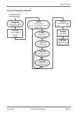
Flow at 20 mA
This setting normally represents the maximum rate of the flow sensor connected to the
display, but other entries are possible�
At the
Fl=20mA
prompt, press
ENTER
� The first digit of the current setting flashes� If the
current setting is correct, press
ENTER
to advance to the next parameter� If the current
setting requires a change, press
UP
to increment the display digit until it matches the
first digit of the required maximum flow value� Press
RIGHT
to advance to the next digit�
Repeat for all of the maximum flow at 20 mA digits� Press
ENTER
to advance to the
4-20Cal
parameter�
In
Programming
mode, the monitor advances to the
Clr G-T
parameter� See
4…20 mA Calibration
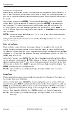
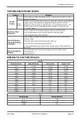
This setting allows the fine adjustment of the Digital to Analog Converter (DAC) that
controls 4…20 mA output� If the output needs to be adjusted for any reason the 4…20 mA
calibration procedure is used�
At the
4-20Cal
prompt, press
ENTER
� The monitor displays No� If you do not need to
complete the 4…20 calibration, press
ENTER
to advance to the
Linear
parameter� See
� To complete the 4…20 calibration, press
UP
or
RIGHT
to
change the display to
Yes
� Press
ENTER
to advance to the 4mA Out parameter�
The DAC used in the B2900 monitor is an twelve bit device� The valid entries are 0…4095�
P1
Freq. In
4-20mA
Iso Total Pluse
RS485 Gnd
Setpoint 1
Setpoint 2
Gnd
+
–
Total Reset
OC Total Pluse
Signal Gnd
TB1
Mag
Pulse
Iso
OC
Low
High
+
+
–
–
Input
Total P
ulse
Sig
nal
JP1
JP2
JP3
RS485 B (–)
RS485 A (+)
4…20 mA
Current Loop
(11…30V DC)
POWER
SUPPLY
10A MAX
FUSED
400mA
FUSED
CAT III
1000V
HOLD
MIN MAX
REL
Hz % ms
RANGE
AutoHOLD FAST MIN MX
LOGGING
YES
CANCEL
SAVE
NO
SETUP
µ
A
mA
A
W
V
TEMPERATURE
COM
OFF
nS
W
VIEW MEM
CLEAR MEM
V
dB
mV
dB
ac+dc
V
ac+dc
A
mA
mV
ac+dc
mA
A
µ
A
ac+dc
µ
A
°C
°F
MEM
HM
MS
51000
AUTO MANUAL
%
FA S T M A X M I N AV G
0
0
LOG
HOLD
Figure 14: 4…20 mA calibration setup


