background image

Programming

Page 34 

May 2020

DSY-PM-01378-EN-08

Bus Address

If the Modbus output is enabled, you must choose a valid Modbus address� Every device 
communicating over the RS485 communications bus using the Modbus protocol must have 
a unique bus address� Address values range from 0…127 with 0 being the default�
At the 

BusAddr

 prompt, press 

ENTER

� The first digit of the address flashes� If the current 

setting is correct, press 

ENTER

 to advance to the next parameter� To change the address, 

press 

UP

 to increment the display digit until it matches the first digit of the new bus 

address� Press 

RIGHT

 to advance to the next digit� Repeat for all digits of the address� Press 

ENTER

 to accept the new address and advance to the 

Baud

 parameter�

Baud

If Modbus is being used, all devices connected to the bus must have the same baud rate 
setting� Baud is expressed as ‘bits per second’ and defines the data transmission speed  
of the network� The B2900 monitor can be changed to use any of the following baud  
rates: 9600, 19200, 38400, 57600 and 115200� See 

“Modbus Interface” on page 44

 for 

additional information�
At the 

Baud

 prompt, press 

ENTER

� The current state of the Baud rate is shown and defaults 

to 9600� If the current state is correct, press 

ENTER

 to advance to the next parameter� To 

change the baud rate setting, press 

UP

 or 

RIGHT

 to scroll through the options� When the 

proper state displays, press 

ENTER

 to advance to the 

SetPt1

 parameter�

Set Points

Set points allow the meter to signal when a specific flow condition has been achieved� They 
are commonly used to indicate high or low flow conditions that need attention� The B2900 
monitor has two open collector outputs controlled by the set point function�
The set point transistors have the same current limitations and setup requirements as the 
totalizing pulse output transistors described previously� See 

Figure 12 on page 30


and 

Figure 13 on page 30

Both set point one and set point two are configured using the same procedures but the 
hysteresis and tripping conditions are independently set for each set point output�

OTE: 

N

In most instances, the current capacity of an open collector transistor is not 
sufficient to operate old style counters that relied on relay contact closures� When 
used with basic counting circuits, a solid-state relay is needed�

Summary of Contents for Blancett B2900

Page 1: ...Digital Flow Monitor B2900 DSY PM 01378 EN 08 May 2020 User Manual...

Page 2: ...Digital Flow Monitor B2900 Page ii May 2020 DSY PM 01378 EN 08...

Page 3: ...d 9 Operating the Monitor 10 Buttons 10 Modes of Operation 11 Programming Using Frequency Output Turbine Flow Meters 11 Enter Programming Mode 11 Menu Structure 12 Liquid 12 Advanced I O Liquid 14 Gas...

Page 4: ...ained 41 Calculating K factors 41 Modbus Interface 44 Modbus Register Word Ordering 45 Specifications 48 Part Number Construction 49 Mounting Options and Dimensions 50 Meter Mount 50 Remote Mount 50 H...

Page 5: ...gy and Symbols Indicates a hazardous situation which if not avoided will result in death or serious personal injury WARNING Indicates a hazardous situation which if not avoided could result in death o...

Page 6: ...with almost any flow sensor producing a low amplitude AC output or contact closure signal Figure 1 B2900 Flow monitor NEMA 4X This monitor can accept low level frequency input signals typically found...

Page 7: ...output signal is type 1 you must also determine the minimum amplitude of the frequency output The B2900 monitor has a high or low signal sensitivity setting Use the high signal sensitivity 30 mV with...

Page 8: ...Typical magnetic pickup connection NEMA 4X For amplified input signals set the input jumper to Pulse and the signal jumper to Low See Figure 4 on page 8 OTE N Amplified magnetic pickups require an ext...

Page 9: ...a 4 20 mA current loop See Figure 5 If the current loop is used a sensing circuit within the monitor detects the presence of the current loop and disconnects the battery from the circuit JP1 JP2 JP3...

Page 10: ...ugh the parameter choices increments numeric variables and increases display contrast in Run mode RIGHT Scrolls forward through the parameter choices moves the active digit to the right and decreases...

Page 11: ...sing Frequency Output Turbine Flow Meters Each Blancett turbine flow meter is shipped with either a K factor value or frequency data If frequency data is provided the data must be converted to a K fac...

Page 12: ...Unt Unit interval T GPT LB T OB T AF T ML T LPT m T Ft T MG T Kg T Lb T Gallons T Liquid Barrel T Oil Barrel T Acre Feet T Million Liters T Liters T Meters T Feet T Million Gallons T Kilograms T Pound...

Page 13: ...Entry Freq x Frequency 2 10 Numeric Entry Coef x Coefficent 2 10 Numeric Entry NO YES Passwd Password Numeric Entry RstPswd Reset Password Numeric Entry Spec Gr Specific Gravity TotlMult Totalizer Mul...

Page 14: ...AF T ML T LPT m T Ft T MG T Kg T Lb T Gallons T Liquor Barrel T Oil Barrel T Acre Feet T Million Liters T Liters T Meters T Feet T Million Gallons T Kilograms T Pounds T MASS TotalUnt Totalizer Unit...

Page 15: ...ric Entry Numeric Entry Numeric Entry Coef 1 Coefficient 1 Numeric Entry Freq x Frequency 2 10 Numeric Entry Coef x Coefficent 2 10 Numeric Entry Modbus Disable Enable Numeric Entry SetPT1 Setpoint 1...

Page 16: ...interval RateUnt Unit interval T SCF T ACF T Nm T Am T Lt T mmF T mF T Standard Ft T Actual Ft T Normal M T Actual M T Liters T Million Ft T Thousand Ft T Shape Key Continued on next page TotlUnt Tot...

Page 17: ...20mA Out 20 mA Output Numeric Entry 4 20Tst 4 20 mA Output Numeric Entry Numeric Entry Numeric Entry Coef 1 Coefficient 1 Numeric Entry Freq x Frequency 2 10 Numeric Entry Coef x Coefficent 2 10 Nume...

Page 18: ...e time interval RateUnt Unit interval T SCF T ACF T Nm T Am T Lt T mmF T mF T Standard Ft T Actual Ft T Normal M T Actual M T Liters T Million Ft T Thousand Ft T Shape Key Continued on next page TotlU...

Page 19: ...0 Numeric Entry Continued from previous page Damping Display Damping Numeric Entry PulsOut Pulse Output Disable Enable Numeric Entry Fl 20mA Flow at 20 mA Modbus Address 1 to127 BusAddr Clr G T Clear...

Page 20: ...Unt Unit interval T GPT LB T OB T AF T ML T LPT m T Ft T MG T Kg T Lb T Gallons T Liquor Barrel T Oil Barrel T Acre Feet T Million Liters T Liters T Meters T Feet T Million Gallons T Kilograms T Pound...

Page 21: ...oef x Coefficent 2 10 Numeric Entry NO YES Passwd Password Numeric Entry RstPswd Reset Password Numeric Entry Spec Gr Specific Gravity TotlMult Totalizer Multiplier 1000 100 10 1 0 1 0 01 1000 100 10...

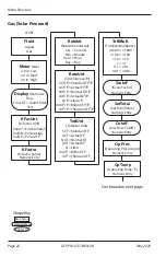
Page 22: ...te time interval RateUnt Unit interval T SCF T ACF T Nm T Am T Lt T mmF T mF T Standard Ft T Actual Ft T Normal M T Actual M T Liters T Million Ft T Thousand Ft T Shape Key Continued on next page Totl...

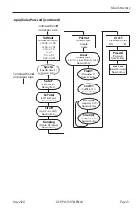
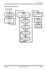
Page 23: ...cy 1 Clr G T Clear Grand Total Numeric Entry Numeric Entry Coef 1 Coefficient 1 Numeric Entry Freq x Frequency 2 10 Numeric Entry Coef x Coefficent 2 10 Numeric Entry NO YES Passwd Password Numeric En...

Page 24: ...MENU button Liquid Select Fluid At the Fluid prompt press ENTER to view the current fluid type If the current fluid type is correct press ENTER to advance to the next parameter To change the fluid ty...

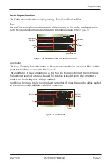
Page 25: ...ous flow rate and current total Grand Total The Flow GT setting forces the meter to alternate between the instantaneous flow and the grand total with roll over counts See Figure 10 The grand total is...

Page 26: ...e to the KFactor parameter Enter Meter s K Factor OTE N The K factor supplied with your meter or calculated from calibration data is needed to complete this step At the KFactor prompt press ENTER The...

Page 27: ...splays the accumulated flow total in multiples of 10 For example if the optimum totalization unit is 1000 gallons the unit total display increments by one digit for every 1000 gallons monitored In Run...

Page 28: ...rates Rather than changing the K factor and linearization parameters individually the scale factor can be set to 1 03 to correct the readings The range of scale factors is from 0 10 5 00 The default...

Page 29: ...to advance to the next digit Repeat for all digits Press ENTER to advance to the Damping parameter OTE N If the number you enter is out of range the display flashes Limit and refuses the entry OTE N I...

Page 30: ...l Reset Total Pluse Signal Gnd Mag Pulse Iso OC Low High RS485 B RS485 A Input Total Pulse Signal TB1 Open Drain FET Total Pulse Output 2 2 10k Pullup Resistor VCC Internal 100 mA Maximum Figure 12 Op...

Page 31: ...is setting allows the fine adjustment of the Digital to Analog Converter DAC that controls 4 20 mA output If the output needs to be adjusted for any reason the 4 20 mA calibration procedure is used At...

Page 32: ...res additional calibration data from the meter being used with the monitor Typically calibration information can be obtained in three five and ten points from the flow meter s manufacturer If lineariz...

Page 33: ...bration Data Table In GPM Actual UUT Frequency UUT Actual K factor Hz x 60 Nominal K Linear Coefficient Raw Error 50 02 gpm 755 900 Hz 906 72 counts US gal 49 72 gpm 1 0060 0 59 28 12 gpm 426 000 Hz 9...

Page 34: ...rface on page 44 for additional information At the Baud prompt press ENTER The current state of the Baud rate is shown and defaults to 9600 If the current state is correct press ENTER to advance to th...

Page 35: ...the first digit of the required set point value Press UP to increment the digit until it matches the first number of the required set point Repeat for all the digits the set point Press ENTER to accep...

Page 36: ...king unexpectedly Trip SP 1 The trip parameter can be set for either High or Lo When set to High the open collector transistor stops conducting and sends the output high when the set point is reached...

Page 37: ...asswd parameter The totalizer can also be reset using a hardware reset as shown in Figure 18 or by pressing MENU and ENTER simultaneously TB1 Mag Pulse Iso OC Low High Input Total Pulse Signal Freq In...

Page 38: ...change the operating pressure press UP to increment the digit until it matches the first digit of the correct pressure value Press RIGHT to move to the next digit When all the digits have been entere...

Page 39: ...amming of flow monitor Flow Rate Display Interprets Reading Constantly This is usually an indication of external noise Keep all AC wires separate from DC wires Check for large motors close to the mete...

Page 40: ...rews on the front panel to gain access to the battery 2 Press the tab on the battery connector to release it from the circuit board 3 Remove the old battery and replace it with new one 4 Re fasten the...

Page 41: ...unts 1000 by the number of seconds in a minute 60 to get the output frequency 1000 60 16 6666 Hz If you were looking at the pulse output on a frequency counter an output frequency of 16 666 Hz would b...

Page 42: ...d is equal to 231 cubic inches Example 3 Known values are Velocity 4 3 ft sec Inside Diameter of Pipe 3 068 in Find the area of the pipe cross section 2 3 068 2 Area r2 Area x 2 35 7 39 in2 Find the v...

Page 43: ...K Factors Explained Page 43 May 2020 DSY PM 01378 EN 08...

Page 44: ...1 8 unit load device input impedance equal to 96 k The RS485 specification states it is capable of supporting 32 standard unit loads 1 standard unit load equals 12 k In order to determine the maximum...

Page 45: ...cription 01 Read Coils 03 1 Read Holding Registers 05 Force Single Coil Table 3 Modbus commands Type Bits Bytes Modbus Registers Long Integer 32 4 2 Single Precision IEEE754 32 4 2 Table 4 Available d...

Page 46: ...ference If the B2900 Totalizer 12345678 hex Register 40106 would contain 5678 hex Word Low Register 40107 would contain 1234 hex Word High Big Endian Data Component Name Modbus Registers Available Uni...

Page 47: ...rm Set point 2 11 and up Spare Table 8 Read coil status Command addr 01 00 08 00 02 crc 16 Reply addr 01 01 0x crc 16 Opcode 03 Read Holding Registers This opcode returns the input holding registers s...

Page 48: ...mp output from sensor Outputs Analog 4 20 mA 4 20 mA two wire current loop 25 mA current limit Totalizing Pulse One pulse for each Least Significant Digit LSD increment of the totalizer Pulse Type sel...

Page 49: ...ity non condensing Materials and Enclosure Ratings Polycarbonate stainless steel polyurethane thermoplastic elastomer acrylic NEMA 4X IP 66 meter remote and swivel mount NEMA UL CSA Type 4X IP 66 Engi...

Page 50: ...25 in 235 0 mm 7 00 in 177 8 mm 5 75 in 146 0 mm 4 00 in 101 6 mm 3 45 in 87 6 mm 1 50 in 38 1 mm 0 875 in 22 2 mm Remote Mount E D A B C 0 25 in dia 6 4 mm 4 HOLES F G H J dia A B C D E F G H I dia...

Page 51: ...Mounting Options and Dimensions Page 51 May 2020 DSY PM 01378 EN 08 Handheld B A C A in mm B in mm C in mm 7 00 177 8 5 75 146 0 4 38 111 2...

Page 52: ...uct improvements and enhancements Badger Meter reserves the right to change product or system specifications without notice except to the extent an outstanding contractual obligation exists 2020 Badge...

Reviews: