Programming
Page 35
May 2020
DSY-PM-01378-EN-08
Set Point 1
The set point is the flow value at which the output transistor changes state� It is set using
the same units as the rate units�
JP1
JP2
JP3
Input
Total P
ulse
Sig
nal
P1
Freq. In
4-20mA
Iso Total Pluse
RS485 Gnd
Setpoint 1
Setpoint 2
Gnd
+
–
+
–
+
–
Total Reset
OC Total Pluse
Signal Gnd
TB1
Mag
Pulse
Iso
OC
Low
High
RS485 B (–)
RS485 A (+)
Open Collector
Control Output
1 and 2
2.2…10K
Pull-up
Resistor
V
CC
Internal
100 mA
Maximum
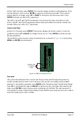
Figure 15: Set point output (NEMA 4X)
At the
SetPt 1
prompt, press
ENTER
� The most significant digit of the current setting flashes�
If the current setting is correct, press
ENTER
to advance to the next parameter� To change
the current setting, press
RIGHT
to advance to the first digit of the required set point value�
Press
UP
to increment the digit until it matches the first number of the required set point�
Repeat for all the digits the set point� Press
ENTER
to accept the new set point and advance
to the
HystSP1
parameter�
Hysteresis 1
The hysteresis parameter modifies how the output transistor reacts around a set point and
prevents an output from turning on and off rapidly when the programmed flow rate is at, or
very near, the set point�
For example, a low flow alarm is set to activate when the flow falls below a
pre-programmed point� When the flow is reduced to the set point, even small changes
of flow above the set point turn the output off, disabling the alarm� Without hysteresis, if
the flow rate fluctuates slightly above and below the set point, the output rapidly cycles
between on and off states� See
� The hysteresis value is set using the
same units as the rate units�

