Replacing the Display Board
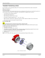
OBSERVE PRECAUTIONS FOR HANDLING ELECTROSTATIC-SENSITIVE DEVICES.
1 . Turn off power to the unit .
2 . Grasp the enclosure cover and turn it counter-clockwise until it separates from the enclosure body . Set the cover aside .
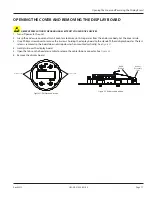
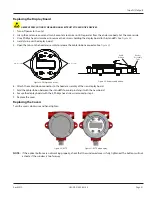
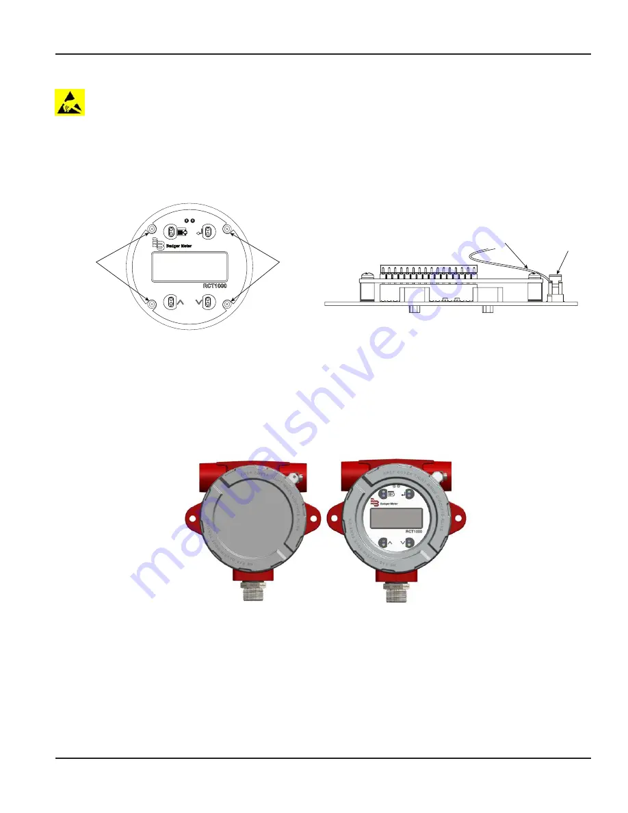
3 . Use a Phillips head screwdriver to remove the 4 screws holding the display board to the standoffs . See
.
4 . Gently turn over the display board .
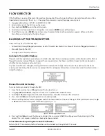
5 . Open the tabs on the header assembly to release the cable ribbon connector . See
.
Remove Screws
Remove Screws
Cable
Ribbon
Header
Assembly
Tabs
Figure 28: Phillips head screws
Figure 29: Release cable ribbon
6 . Attach the cable ribbon connector to the header assembly of the new display board .
7 . Fold the cable ribbon between the standoffs to avoid pinching it with the new board .
8 . Secure the display board with the 4 Phillips head screws removed in step 3 .
9 . Replace the cover .
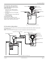
Replacing the Covers
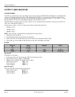
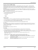
Turn the covers clockwise and hand-tighten .
Figure 30: RCTX
Figure 31: RCTX with display
OTEE:
N
If the optical buttons are not working properly, check that the windowed cover is fully tightened . The buttons will not
activate if the window is too far away .
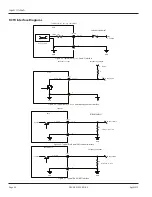
Inputs / Outputs
Page 21
April 2019
CRL-QS-01552-EN-05


