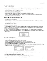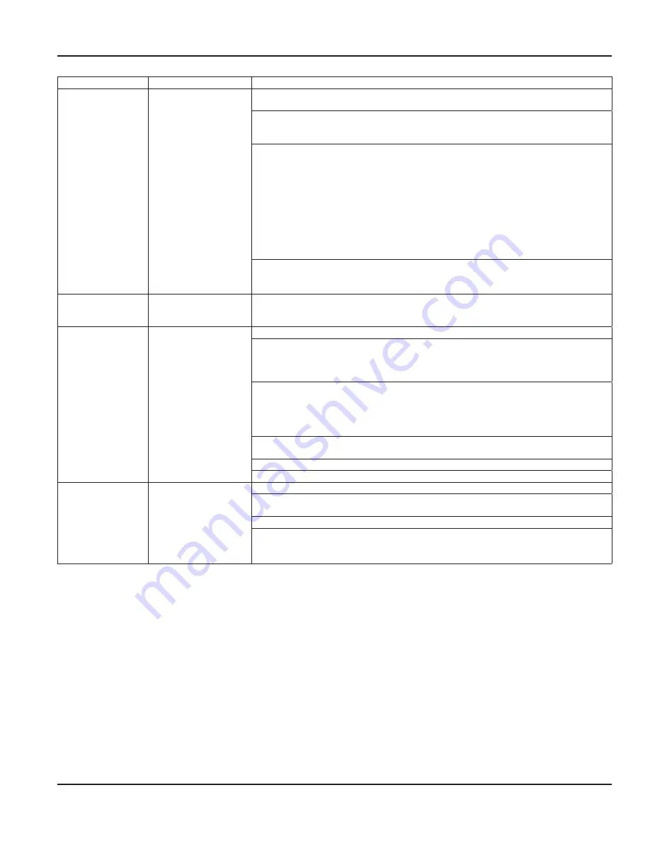
Symptom
Possible Cause
Recommended Action
Density reading
appears to be
incorrect
Installation issues
Process loop issues
Incorrect
parameter settings
Check process loop for entrained air and concentration of mix fluids which will impact
the density .
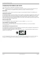
Run HealthTrack, the advanced function in RCT Console configuration software, to record
critical measurements . Multiple, vital parameters can be viewed in a single snapshot to
assist with diagnosing issues .
Check for mechanical vibrations . Impact of mechanical vibrations might be visible in
the parameters .
System > Sensor >
DrvOut
and
Freq
(tube frequency) readings .
DrvOut
should be between
10…95% and
Freq
should be between:
• 90…115 Hz (RCS005)
• 170…220 Hz (RCS008)
• 80…110 Hz (RCS018…050)
• 40…90 Hz (RCS100…300)
OTEE:
N
The frequency stability should be better than ± 0 .01 Hz for a
good measurement
Verify that the calibration factors on the sensor are entered correctly to the transmitter:
• Set Up > Calibration > Flow >
FloFct
(Flow Factor)
• Set Up > Calibration > Density parameters:
DAlpha
and
DBeta
Volumetric flow
reading appears to
be incorrect
Mass or density
readings are incorrect
Volumetric flow rate is calculated the mass flow rate divided by the density:
vFlo = mFlo/Dens
Sensor temperature
(Temp1) reading
appears to be
incorrect
Incorrect wiring
Cable issue
RTD not functioning
Verify sensor RTD is properly wired to transmitter (pins 2, 3 and 4) .
At the transmitter, disconnect the sensor wiring . Measure the resistance between brown
and yellow/gray sensor wires . The resistance should be approximately 110 Ohms at
77° F (25° C) . The resistance will vary depending on the fluid temperature . The resistance
between the yellow and gray sensor wires should be less than 5 Ohms .
If there appears to be an open or short at the transmitter end of the cable, remove the
sensor cable from the sensor and measure the resistance from pin J to pins G/H on the
sensor . The resistance should be 80…100 Ohms for temperatures less than 32° F (0°
C) and 100…180 for temperatures greater than 32° F (0° C) . Depending on the fluid
temperature, the resistance between pins G and H should be less than 1 Ohm .
Check the RTD Calibration constants in
Set Up > Calibration > Temperature
.
RTD1Of
should
be 0 (± 5) .
RTD1Sl
should be 1 .00 (± 0 .1) .
If there appears to be an open or short at the pins, replace the sensor .
If the sensor measurements are in the acceptable range, replace the sensor cable .
Current, frequency,
pulse or PWM
outputs do not
match the readings
Incorrect
parameter settings
Wiring
configuration issues
Control system
configuration issues
See
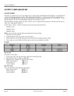
"Output Configuration" on page 32
for parameter settings .
Check that the ID parameter for the output matches the parameter of the
desired reading .
Verify that the minimum and maximum parameters for the output are set properly .
Verify the device reading the output is set up correctly . The current and frequency
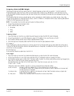
outputs have a test output (
TstOut
) that can be used to troubleshoot system issues .
Table 3: Troubleshooting symptoms/resolution
Troubleshooting
Page 39
April 2019
CRL-QS-01552-EN-05


