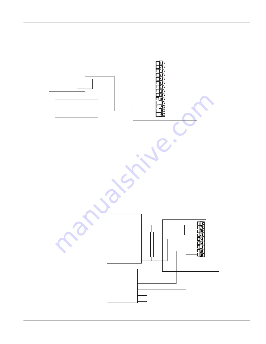
Normally Open Solid-State Switch
Mechanical
Counter
Power Supply
(Appropriate Mechanical Counter)
Typically 12V DC
(-)
(+)
Relay 1 NO
Relay 1 NC
Relay 1 COM
Relay 2 NO
Relay 2 NC
Relay 2 COM
Relay 3 NO
Relay 3 NC
Relay 3 COM
Relay 4 NO
Relay 4 NC
Relay 4 COM
Pulse 1 OUT
Pulse 1 OUT
Sensor Input Card
Red Label
14 Pin Connector
NOTEE:
Although the example shown here is showing the Pulse Output as a Pulse/Unit Volume, this output is a fully functional relay,
with all the programming feature of the four mechanical relays. However, instead of a Form C mechanical, it is a Form A Solid-State Switch (NO).
1
2
3
4
5
6
7
8
9
10
11
12
13
14
Figure 9: External mechanical counter and power supply
The pulse output is a completely programmable, isolated N .O . solid-state switch .
It is a non-polarized device that can handle either DC or AC loads . See
for voltage and
load limitations .
Analog Outputs
The Series 3100 flow monitor has two analog outputs . Each is isolated and independent and can be configured for 0…20 mA
or 4…20 mA . This unique design permits external conversion to 0…5V DC or 1…5V DC with a 250 Ohm resistor or 0…10V DC
or 2…10V DC with a 500 Ohm resistor .
A 15V DC power supply to permits current sinking or sourcing . If additional source voltage is required, an external source of
up to 30V DC can be used .
Analog Input Device
12V max. @20 mA
Analog (+)
Analog (-)
NOTEE:
Resistor only required
for voltage input devices
0 . . . 1V DC, 0 . . . 5V DC,
1 . . . 5V DC, 2 . . . 10V DC, etc.
0 . . . 20 mA and 4 . . . 20 mA
devices do not use an
external resistor.
Analog Input Device
with External or Integral
Power Supply
24V DC (+)
Analog IN (+)
Analog IN (-)
Power Supply COM
Analog Output Card
Yellow Label
9 Pin Connector
R
e
s
i
s
t
o
r
RS485 B (+)
RS385 A (-)
RS485 Iso. GND (REF)
CH2 Loop (+)
CH2 Loop (-)
CH2 GND
CH1 Loop (+)
CH1 Loop (-)
CH1 GND
1
2
3
4
5
6
7
8
9
NOTESE:
4 . . . 20 mA input devices only require that
the 4 . . . 20 mA range be selected.
0 . . . 1V DC requires 0 . . . 20 mA range and
external 50 Ohm resistor.
0 . . . 5V DC requires 0 . . . 20 mA range and
external 250 Ohm resistor.
2 . . . 10V DC requires 0 . . . 20 mA range and
external 500 Ohm resistor.
1.
2.
Loop (+) is +15V DC power our.
Loop (-) is a current sink to CHx GND.
CHx GND is the +15V reference.
3.
Analog Out #1 and Analog #2 are totally
independent but are programmed and
wired identically, and can be used
interchangeably. For example, one
can be 0 . . . 20 mA and the other
4 . . . 20 mA; or one could be wired
current sinking while the other is
wired current sourcing.
The Output Channels are assigned to an
Input Channel by the installer. Both Output
Channels can be assigned to the same
Input Channel.
Figure 10: Current sourcing analog output to voltage input device
Installation
Page 11
October 2017
CTL-UM-01026-EN-05


