Installing a Meter with a Remote Transmitter and Fixed Transducers
• Locate the transmitter within the length of the transducer cables supplied or exchange the cable for one of proper length
• See
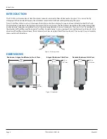
for enclosure and mounting dimension details Allow enough room for door swing, maintenance
and conduit entrances
MPORTANT
I
When routing wires to the transmitter, make sure the cables are not twisted, pinched or hanging loosely.
1 Install the
fixed
transducers according to instructions in the transducer user manual
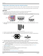
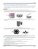
2 Partially loosen the 2 enclosure captive screws on the left side of the transmitter cover Completely loosen the 2 screws on
the right side Grasp and lift the cover and open it to the left The cover remains attached and the left screws act as a hinge
Unscrew
Captive Screws
Figure 3: Captive cover screws
Figure 4: Lift cover from base
Figure 5: Open cover to the left
3 Unscrew the wingnut from the threaded stud on the inside back of the enclosure to release the adapter plate Set aside
the wingnut
Figure 6: Rotatable adapter plate
4 If necessary, rotate the adapter plate by 90° to accommodate the final orientation of the transmitter
5 Mount the adapter plate either to a wall (with 4 customer-supplied #8 or M4 screws) or to a pipe (with mounting straps)
Holes for
Screws
Holes for
Screws
Holes for Straps
Figure 7: Wall mount
Figure 8: Pipe Mount
6 Use conduit holes where cables enter the enclosure from the bottom Use plugs to seal any holes that are not used for
cable entry A cable gland kit is included for inserting the transducer and power cables
OTE:
N
Use NEMA 4 (IP-66) rated fittings/plugs to maintain the watertight integrity of the enclosure Generally, the right
conduit hole (viewed from front) is used for power, the left conduit hole for transducer connections, and the center
hole is used for I/O wiring
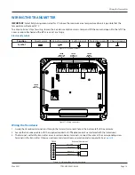
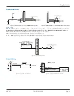
7 Install the wires through the gland nuts and connect the wires to the removable terminal blocks See
8 Wire the transducers to the transmitter
9 Slide the meter enclosure over the threaded stud and secure it with the wingnut
10 Plug the wired terminal blocks into the main board
11 Reassemble the cover
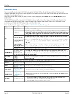
12 Set up the meter See
“Initial Meter Setup” on page 16
for instructions
Installation
Page 10
May 2021
TTM-UM-02537-EN-06


