Installing a Meter with an Integral Transmitter
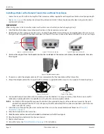
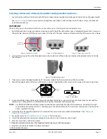
1 Install the meter on the pipe according to the instructions in the user manual for your particular transducer
Pipe
Figure 15: Install the meter onto the pipe
2 Partially loosen the 2 enclosure captive screws on the left side of the transmitter cover Completely loosen the 2 screws on
the right side Grasp and lift the cover and open it to the left The cover remains attached and the left screws act as a hinge
3 If necessary, rotate the transmitter 180° by opening the cover, loosening the wing nut, repositioning the transmitter, and
reinstalling all of the connections
4 Use conduit holes where cables enter the enclosure from the bottom Use plugs to seal any holes that are not used for
cable entry A cable gland kit is included for inserting the transducer and power cables
OTE:
N
Use NEMA 4 (IP-66) rated fittings/plugs to maintain the watertight integrity of the enclosure Generally, the right
conduit hole (viewed from front) is used for power, the left conduit hole for transducer connections, and the center
hole is used for I/O wiring
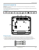
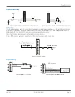
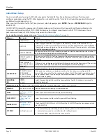
5 Install the wires through the gland nuts and connect the wires to the removable terminal blocks See
6 Plug the wired terminal blocks into the main board
7 Reassemble the cover
Wiring the Transmitter
Page 12
May 2021
TTM-UM-02537-EN-06


