WIRING THE TRANSMITTER
IMPORTANT
: Select field wiring means rated for 5° C above the maximum area temperature when it is possible that the
temperature will exceed 55° C
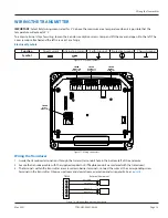
To access terminal strips for wiring, loosen the 4 enclosure captive screws Grasp and lift the cover and open it to the left The
cover remains attached and the left screws act as a hinge
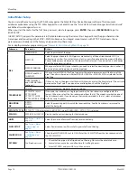
Electrical Symbols
Function
Direct Current
Alternating Current
Earth (Ground)
Protective Ground
Chassis Ground
Symbol
Figure 16: Electrical symbols
TOTAL
RESET
ENC CLK IN
ENC DOUT
UP
STREAM
DOWN
STREAM
24V OUT
4-20 L
OOP
4-20 OUT
RS-485
CONTROL
OUT
1 2
9 - 28V DC
@ 5W (Max)
TB300
Transducer
Connector
TB400
Power
Connector
TB600
Output
Connector
TB500
Digital I/O
Connector
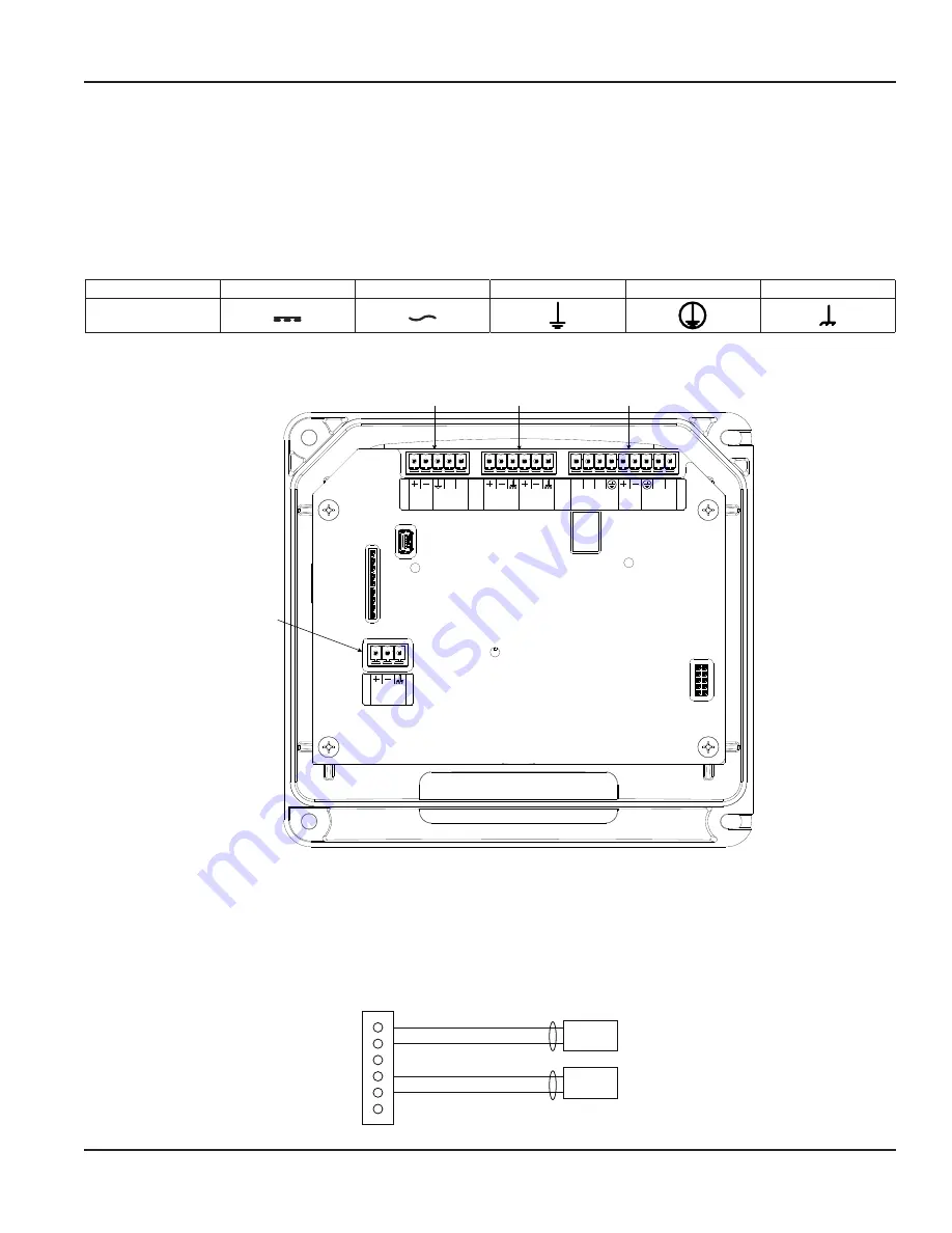
Figure 17: Wiring connectors
Wiring the Transducer
1 Guide the transducer terminations through the transmitter conduit hole in the bottom-left of the enclosure
2 Secure the transducer cable with the supplied conduit nut (if flexible conduit was ordered with the transducer)
3 The terminals within the transmitter are screw-down barrier terminals Connect the wires at the corresponding screw
terminals in the transmitter Observe upstream and downstream orientation and wire polarity See
1
2
3
TB300
External Equipment
UP/TX Red
4
5
6
DN/TX Red
UP/TX Black
DN/TX Black
Figure 18: Upstream/downstream transducer
Wiring the Transmitter
Page 13
May 2021
TTM-UM-02537-EN-06


