REPLACEMENT INSTRUCTIONS
This product cannot be repaired by the user and must be replaced with an equivalent certified product Repairs are only
allowed to be carried out by the manufacturer or its authorized agent
Front Panel Replacement
A replacement front panel assembly
with
display/keypad (PN D080-1020-001) is available and includes the front cover,
display/keypad/overlay, main board, connectors and shield A replacement front panel assembly
without
the display/keypad
(PN D080-1020-002) is also available It includes the front cover, main board, connectors and shield
The front panel is a single piece and is easily removed by unscrewing the four enclosure screws Turn off the power before
replacing the front panel
Main Board Replacement
Replacing the
complete
transmitter or the front panel as a
single piece
is the preferred method However, you can replace only
the main board (PN D020-2100-005), if necessary Instructions follow
CONTAINS PARTS AND ASSEMBLIES SUSCEPTIBLE TO DAMAGE BY ELECTROSTATIC DISCHARGE (ESD). BEFORE PICKING
UP AN ESD-SENSITIVE ELECTRONIC COMPONENT, DISCHARGE YOURSELF BY TOUCHING A GROUNDED BARE METAL
SURFACE OR APPROVED ANTI-STATIC MAT.
OBSERVE PRECAUTIONS FOR HANDLING ELECTROSTATIC-SENSITIVE DEVICES.
Tools Required
• A Philips #2 screwdriver
• A flat blade screwdriver
• Tweezers for electronics
• A workbench that prevents ESD damage to the electronics
To remove the main board:
1 Turn off the power
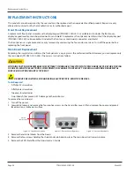
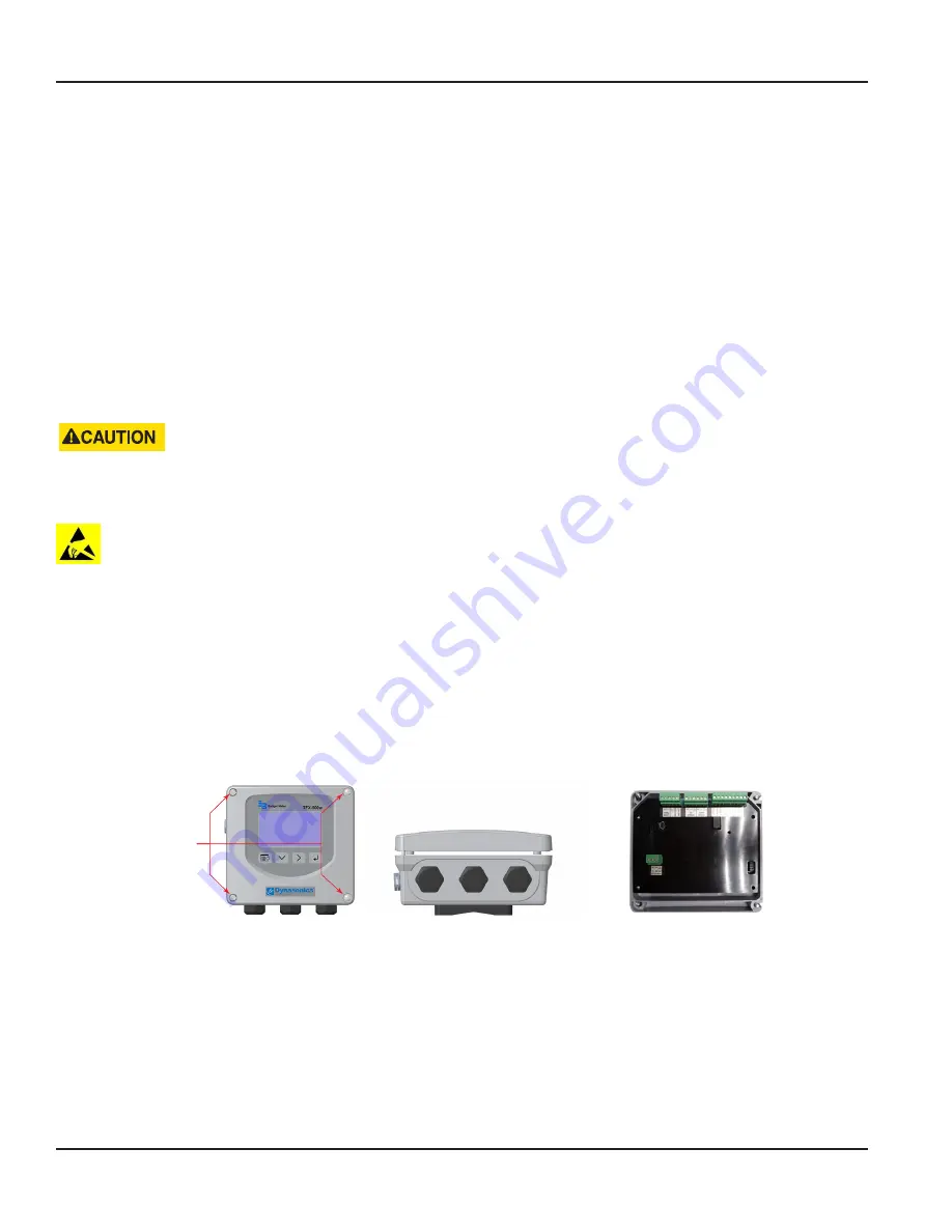
2 Completely loosen and remove the four captive screws on the transmitter cover Lift and remove the cover and place it
face down on a stable work surface
Unscrew
Captive Screws
Figure 30: Captive cover screws
Figure 31: Remove cover from base
Figure 32: Lay cover face down
3 Remove the terminal blocks from the board
4 Remove the four screws holding the shield and main board in place The main board will remain in place
5 Remove the PCB shield from the board and set it aside
Replacement Instructions
Page 36
May 2021
TTM-UM-02537-EN-06


