background image

ESM-UM-03099-EN-02

•  METERS MUST OPERATE IN A COMPLETELY FILLED LINE AT ALL TIMES. THE DOWNSTREAM PIPING MUST 

ALWAYS BE ARRANGED TO PROVIDE SUFFICIENT BACK PRESSURE TO MAINTAIN A FULL LINE AT THE METER. BY 

ELIMINATING AIR IN THE LINE, AS WELL AS SUDDEN FLOW SURGES, INACCURATE REGISTRATION AND DAMAGE TO 

THE METER CAN BE AVOIDED.

Pre-Installation

Take into account the following considerations before you begin an E-Series Ultrasonic meter installation:
•  Inspect the piping around the meter for suitable conditions  The service line, valves, connections and meter must be 

watertight  Repair the piping system if pipes are corroded or damaged  

•  Install the meter in the pipeline in a horizontal or vertical position so that the flow arrow on the meter housing points in 

the same direction as water flow  Registration should be upright and protected from damage, freezing and tampering 

•  Verify meters are correctly programmed  
•  Position the meter so it is accessible for installation, removal and reading 
•  The line opening for the meter should match the lay length of the meter, allowing slight additional space for coupling 

gaskets  The inlet and outlet sides of the meter should be axially aligned to the pipe 

•  The installed meter must not be an obstacle or a hazard to the customer or interfere with public safety  
•  To avoid cavitation, always install control valves downstream of the meter  Never install the meter on a pump suction side 
•  Consider maximum flow rates when sizing and selecting the appropriate meter for the application  
•  Pump discharge should never be installed in proximity of the meter 
•  Externally weighted check valves and pressure reducing devices should not be located in proximity of the meter  

Installation Instructions

1   Begin at this step when cutting in for new service  When cutting in is not required, begin at 

step 2


• 

Close the curb (shutoff) valve to relieve water pressure in the line before starting the cutting operation  Provide a 

high-quality upstream shutoff valve with a low pressure drop  

• 

Flush the pipe to clear chips, pipe dope or other plumbing residue 

2   Close the meter inlet-side valve  
3   Open a faucet and wait until water flow stops to depressurize the system  Do not remove the meter until the flow stops  

DEPRESSURIZE THE LINE BEFORE STARTING ANY DISASSEMBLY OPERATION. REMOVING A METER THAT IS UNDER 

LINE PRESSURE CAN RESULT IN COMPONENTS BECOMING PROJECTILES, CAPABLE OF CAUSING PERSONAL INJURY. 

4   Check valves and make necessary repairs to the curb (shutoff) valve or inlet side valve if necessary  
5   Before installing or removing a meter, close the outlet-side valve to relieve pressure  Protect the area around the meter 

against potential spills or leaks that could occur  

6   To replace an existing meter continue with 

step 7

  To install a new meter skip to 

step 9


7   Loosen the meter coupling nuts or flange bolts, and remove the meter and old gaskets  
8   Clean the coupling nuts or flange bolts, removing any pipe dope or dirt  
9   Check the existing position for proper alignment and spacing  Correct any misalignment or spacing issues  
10   Place the connection gaskets inside the connection coupling nuts  
11   Install the meter in the pipeline in a horizontal or vertical position with the


flow arrow on the meter pointing in the 

direction of flow

  Registration should be upright  

continued on next page

Installation

Page 7 

May 2021

Summary of Contents for E G2 Series

Page 1: ...E Series G2 Ultrasonic Meter Lead Free Bronze Alloy 5 8 x 3 4 inch ESM UM 03099 EN 02 May 2021 User Manual...

Page 2: ...gs and Accessories 5 Removing a Meter 5 Meter Operating Modes 6 Installation 6 Outdoor Installations 6 Indoor Installations 6 Pre Installation 7 Installation Instructions 7 Operations 9 Display 9 Acti...

Page 3: ...optional integrated pressure sensor Applications E Series Ultrasonic meters measure potable cold water in residential applications The meter is also ideal for non potable reclaimed irrigation water a...

Page 4: ...ure 2 Water Pressure and Temperature sensors selection 3 Select the Water Pressure and or Water Temperature check boxes to turn on reporting for the temperature and or pressure meter sensors 4 Select...

Page 5: ...ble use in reshipment or storage Visually inspect the meter and applicable accessory devices for any signs of damage such as scratches loose or broken parts or other physical damage that may have occu...

Page 6: ...ter box is properly bedded so that it is not axially misaligned and that it lays evenly on the bottom of the pipe trench Place the backfill material covering the pipe appropriately to maintain pipe al...

Page 7: ...of the meter Externally weighted check valves and pressure reducing devices should not be located in proximity of the meter Installation Instructions 1 Begin at this step when cutting in for new serv...

Page 8: ...r appropriate for the meter size the better Take caution when opening the inlet valve to avoid damage to the pressure sensor due to extreme water hammer 13 Slowly open the outlet valve until air is ou...

Page 9: ...e alarms and temperature and pressure data are sent as part of the encoder message and surfaced in BEACON AMA when meter is used with ORION Cellular LTE M LTE MS or LTE endpoints Activating the Displa...

Page 10: ...h ft3 123456 78 10 ft3 123456 7 1 ft3 123456 10 ft3 12345 Typical Billing Units 100 ft3 1234 Cubic Meters Meter reading to the nearest 10000th m3 12345 6789 1000th m3 12345 678 100th m3 12345 67 10th...

Page 11: ...s stored in this position until reported to the endpoint Up to 15 min with ORION Cellular Position 1 Position 2 Position 3 Figure 10 Alarm and operating mode screen in transition mode Up to 1 hr with...

Page 12: ...rted to Reading Software ORION Cellular 9 digit reading plus the extended message capability ORION Migratable ME Fixed Network SE 8 digit reading plus the extended message capability ORION Classic CE...

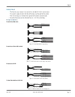
Page 13: ...Encoder and Scaled Unscaled RED Scaled Pulse GREEN Unscaled Pulse BLACK Ground Encoder cable with in line connector Scaled unscaled cable with flying lead RED Scaled Pulse GREEN Unscaled Pulse BLACK G...

Page 14: ...ally filled pipe Last known good read is displayed If the meter is active and detects an empty pipe water temperature displays ErrF or ErrC If meter is in storage mode and detects an empty pipe water...

Page 15: ...lert Measurement error 004 End of life 013 Empty pipe Temperature Reverse flow 100 Pressure 008 No usage 018 No usage Reverse flow 101 Empty pipe Pressure 009 Empty pipe No usage 020 Suspected leak 14...

Page 16: ...ing permanently sealed electronic LCD digits are 0 28 in 7 mm high Register Display Total consumption nine digits Unit of measure factory programmed for gallons cubic feet and cubic meters Rate of flo...

Reviews: