background image

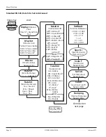
MENU STRUCTURE

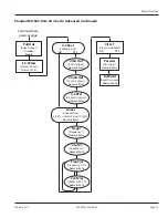
Standard ER-500, Rate SU is Set to Simple

Numeric Entry 

KFactor

(K-Factor Value) 

KFacUnt

(K-Factor Unit)

START

Basic Menu

Extended Menu

Sub Menu

Pul/Gal

Pul/m³

Pul/Ltr

Pul/Ft³

=

=

=

=

Pulses/Gallon

Pulses/meter³

Pulses/Liter

Pulses/Ft³

Shape Key

Rate SU

(Rate Unit Setup)

Simple   

Advanced

Flo Unt

(Rate/Total Units)

GPM

Gal

OB/D

BBL

m³/D

m³/H

LPM

Ltr

=

=

=

=

=

=

=

=

=

=

Gallons/Min

Gallons

Oil Barrel/Day

Barrels

Meters³/Day

Meters³

Meters³/Hour

Meters³

Liters/Min

Liters

PulsOut

(Pulse Output) 

Disable

Enable

Numeric Entry 

Fl=20mA

(Flow at 20 mA) 

Clr G-T

(Clear Grand Total)

NO

YES

Passwd

(Password)

Numeric Entry

RstPswd

(Reset Password)

Numeric Entry

Menu Structure

DSY-PM-00028-EN-02

Page 10 

February 2017

Summary of Contents for ER-500

Page 1: ...Display ER 500 Advanced DSY PM 00028 EN 02 February 2017 Programming Manual...

Page 2: ...ER 500 Flow Monitor Page ii February 2017 DSY PM 00028 EN 02...

Page 3: ...9 Programming Using Frequency Output Flow Sensors 9 Menu Structure 10 Standard ER 500 Rate SU is Set to Simple 10 Advanced ER 500 Basic Menu 11 Standard ER 500 Rate SU is Set to Advanced 12 Advanced E...

Page 4: ...ER 500 Flow Monitor Page iv February 2017 DSY PM 00028 EN 02...

Page 5: ...avoided could result in severe personal injury or death Indicates a hazardous situation which if not avoided is estimated to be capable of causing minor or moderate personal injury or damage to proper...

Page 6: ...a frequency output The output signal for these type of sensors is a frequency proportional to the rate of flow The ER 500 monitor uses the frequency information to calculate flow rate and total flow...

Page 7: ...e that came with the IOG meter For instructions on programming the K factor see Enter Flow Sensor s K factor on page 17 Transmitter Connections The ILR transmitter typically used with the IOG meter fa...

Page 8: ...he current loop is used a sensing circuit within the monitor detects the presence of the current loop and automatically disconnects the battery from the circuit JP1 JP2 JP3 Input Total Pulse Signal P1...

Page 9: ...hen the grand total Modes RUN Normal operating mode PROGRAM Used to program parameters in the display EXTENDED PROGRAMMING Used to program advanced variables into the display TEST Used as a diagnostic...

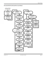
Page 10: ...ape Key Rate SU Rate Unit Setup Simple Advanced Flo Unt Rate Total Units GPM Gal OB D BBL m D m m H m LPM Ltr Gallons Min Gallons Oil Barrel Day Barrels Meters Day Meters Meters Hour Meters Liters Min...

Page 11: ...rs T Meters T Feet T Million Gallons T Kilograms T Pounds T MASS TotalUnt Totalizer Unit Gal LBL OBL AFt MLt LPT m Ft MGa Kgs Lbs Gallons Liquor Barrel Oil Barrel Acre Feet Million Liters Liters Meter...

Page 12: ...rel T Oil Barrel T Acre Feet T Million Liters T Liters T Meters T Feet T Million Gallons T Kilograms T Pounds T MASS TotalUnt Totalizer Unit Gal LBL OBL AFt MLt LPT m Ft MGa Kgs Lbs Gallons Liquor Bar...

Page 13: ...Output Numeric Entry 4 20Tst 4 20 mA Output Numeric Entry Numeric Entry Numeric Entry Coef 1 Coefficient 1 Numeric Entry Freq x Frequency 2 10 Numeric Entry Coef x Coefficent 2 10 Numeric Entry NO YE...

Page 14: ...t T Million Liters T Liters T Meters T Feet T Million Gallons T Kilograms T Pounds T MASS TotalUnt Totalizer Unit Gal LBL OBL AFt MLt LPT m Ft MGa Kgs Lbs Gallons Liquor Barrel Oil Barrel Acre Feet Mi...

Page 15: ...e Output Disable Enable Numeric Entry Fl 20mA Flow at 20 mA Continued from previous page Modbus Address 1 to127 BusAddr Clr G T Clear Grand Total Passwd Password Modbus Disable Enable Numeric Entry Se...

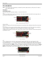
Page 16: ...in addition to the current total totalizer on the display and is always enabled In addition the grand total screen displays the number of times the grand total has reached its maximum count 9 999 999...

Page 17: ...ompt press ENTER The monitor flashes the current total units If the current selection is correct press ENTER to advance to the next parameter To change to an alternate unit press UP or RIGHT to scroll...

Page 18: ...Cutoff parameter NOTE N If the number you enter is out of range the display flashes Limit and refuses the entry Low Flow Cutoff The flow cutoff shows low flow rates that can be present when pumps are...

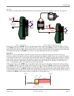
Page 19: ...oint 2 Gnd Total Reset Total Pluse Signal Gnd Mag Pulse Iso OC Low High Input Total Pulse Signal TB1 Open Drain FET Total Pulse Output 2 2 10K Pull up Resistor VCC Internal 100 mA Maximum Figure 9 Ope...

Page 20: ...tment To set the 4mA Out value connect an ammeter in series with the loop power supply as shown in Figure 11 The 4 mA DAC setting is typically 35 50 At the 4mA Out prompt press UP to increase or RIGHT...

Page 21: ...ance to the Coef 1 parameter Coefficient The coefficient is the value applied to the nominal K factor to correct it to the exact K factor for that point The coefficient is calculated by dividing the a...

Page 22: ...nt the display digit until it matches the first digit of the new bus address Press RIGHT to advance to the next digit Repeat for all digits of the address Press ENTER to save the new address and advan...

Page 23: ...transistor reacts around a setpoint by taking recent history into account Hysteresis prevents an output from turning on and off rapidly when the programmed flow rate is at or very near the setpoint Fo...

Page 24: ...um Flow Output ON O F F 8 g p m S e t p o i n t 1 0 g p m Hysteresis 2 gpm Output OFF Figure 15 Setpoint example At the TripSP1 prompt press ENTER The tripping condition setting is displayed If the cu...

Page 25: ...ulses when the count total reached 1000 you would have accumulated 1 gallon of liquid Using the same reasoning each individual pulse represents an accumulation of 1 1000 of a gallon This relationship...

Page 26: ...values are Velocity 4 3 ft sec Inside Diameter of Pipe 3 068 in Find the area of the pipe cross section 2 3 068 2 Area r2 Area x 2 35 7 39 in2 Find the volume in 1 ft of travel 88 71in2 7 3 in2 x 12...

Page 27: ...which order the words are sent as long as the receiving device knows which way to expect it Since word order is a common problem between devices many Modbus master devices have a configuration setting...

Page 28: ...the OFF state 3 8 Spares Alarm Setpoint 1 9 0 Setpoint OFF 1 Setpoint ON Alarm Setpoint 2 10 0 Setpoint OFF 1 Setpoint ON 11 16 Spares Opcode 01 Read Coil Status This opcode returns the state of the...

Page 29: ...ess the tab on the battery connector to release it from the circuit board see Figure 18 Freq In 4 20mA Iso Total Pluse TR_B TR_A RS485 Gnd Setpoint 1 Setpoint 2 Gnd Total Reset OC Total Pluse Signal G...

Page 30: ...sistor Adjustable flow rate with programmable dead band and phase Maximum Voltage 28V DC Maximum Current 100 mA Pull Up Resistor External required 2 2 K ohm minimum 10 K ohm maximum Modbus Advanced On...

Page 31: ...voltage is checked across or in parallel with the 4 20 mA terminals and current is checked with the ammeter in series with the 4 20 mA output No Rate or Total Displayed Check connection from meter s t...

Page 32: ...ENTRIE THROUGH SUITA STRAIGHT THRU 5 WHEN SELECTING CABLE FOR CONNECTION TO TURBINE METER USE CABLE WITH THE FOLLOWING HAZARDOUS LOCATION 10 FT TO MAX 100 FT HAZARDOUS LOCATION CLASSIFIED CLASS I DIV...

Page 33: ...THROUGH SUITABLY SIZED UL CSA CERTIFIED LIQUID TIGHT STRAIGHT THRU FITTINGS NOTES ON FLOW SENSOR 1 INTERCONNECTING CABLE CAPACITANCE AND INDUCTANCE PLUS THE CAPACITANCE AND INDUCTANCE OF THE MAGNETIC...

Page 34: ...Display ER 500 Advanced INTENTIONAL BLANK PAGE DSY PM 00028 EN 02 Page 34 February 2017...

Page 35: ...Programming Manual INTENTIONAL BLANK PAGE DSY PM 00028 EN 02 Page 35 February 2017...

Page 36: ...2 55 5662 0882 Europe Middle East and Africa Badger Meter Europa GmbH Nurtinger Str 76 72639 Neuffen Germany 49 7025 9208 0 Europe Middle East Branch Office Badger Meter Europe PO Box 341442 Dubai Sil...

Reviews: