SPECIFICATIONS
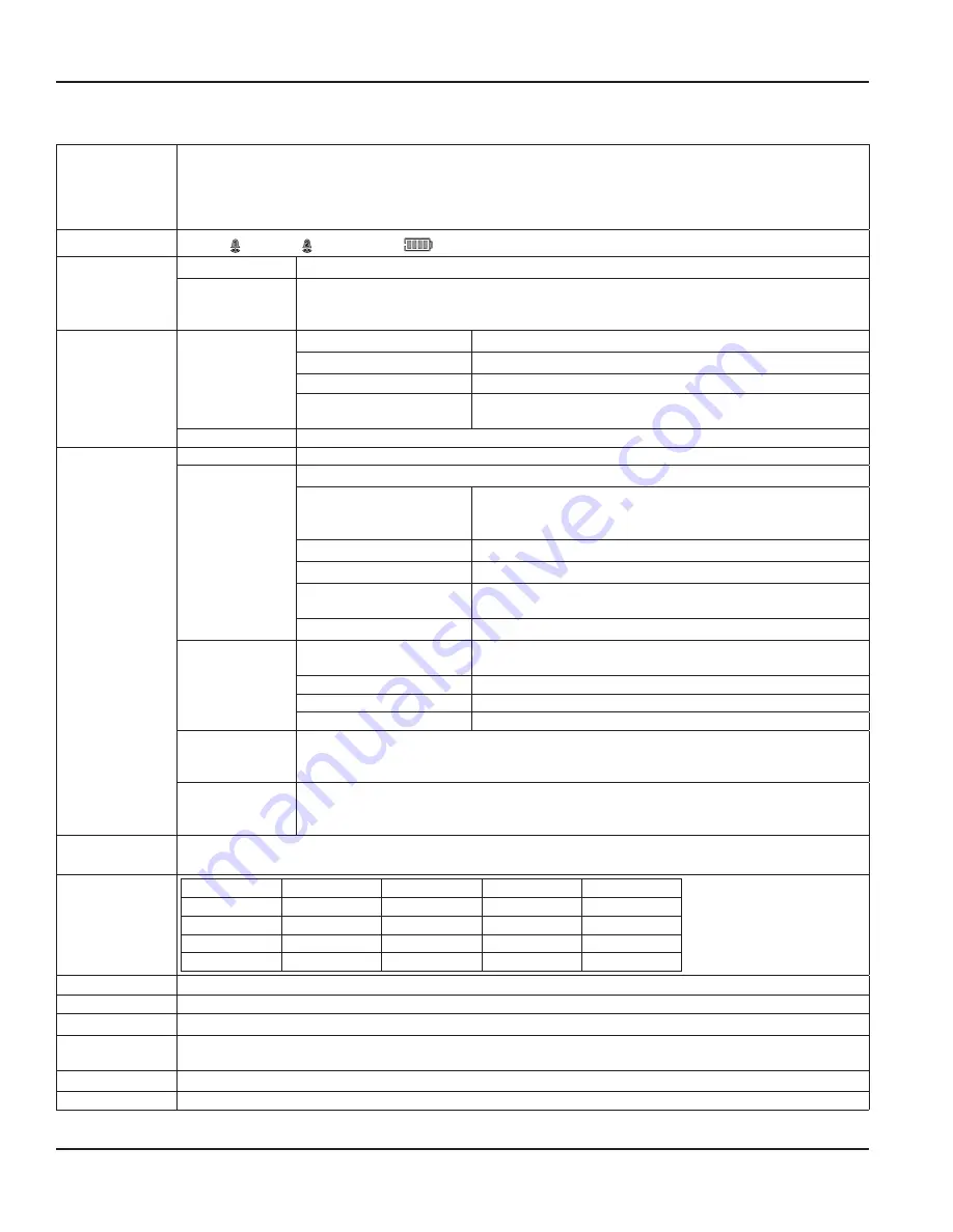
LCD
Simultaneously shows Rate and Total
5 x 7 Dot matrix LCD, STN fluid
6 Digit rate, 0 5 inch (12 7 mm) numeric
7 Digit total, 0 5 inch (12 7 mm) numeric
Engineering unit labels 0 34 inch (8 6 mm)
Annunciators
Alarm 1(
1
), Alarm 2 (
2
), Battery Level (
), RS485 Communications (
COM
)
Power
Battery
3 6V DC lithium “D Cell” gives up to 6 years of service life
Loop
4…20 mA, two wire, 25 mA limit, reverse polarity protected, 7 V DC loop loss
Auto switching between internal battery and external loop power; includes isolation between
loop power and other I/O
Inputs
Magnetic Pickup
Frequency Range
1…3500 Hz
Frequency Accuracy
±0 1%
Over Voltage Protection
28V DC
Trigger Sensitivity
30 mVp-p (High) or 60 mVp-p (Low) - (selected by circuit board
jumper)
Amplified Pulse
Direct connection to amplified signal (pre-amp output from sensor)
Outputs
Analog 4…20 mA 4…20 mA, two-wire current loop 25 mA current limit
Totalizing Pulse
One pulse for each Least Significant Digit (LSD) increment of the totalizer
Pulse Type
(selected by circuit board
jumper)
Opto-isolated (Iso) open collector transistor
Non-isolated open drain FET
Maximum Voltage
28V DC
Maximum Current Capacity 100 mA
Maximum Output
Frequency
16 Hz
Pulse Width
30 mS fixed
Status Alarms
(Advanced Only)
Type
Open collector transistor Adjustable flow rate with programmable
dead band and phase
Maximum Voltage
28V DC
Maximum Current
100 mA
Pull-Up Resistor:
External required (2 2 K ohm minimum, 10 K ohm maximum)
Modbus
(Advanced Only)
Modbus RTU over RS485, 127 addressable units / 2-wire network, 9600 baud, long integer and
single precision IEEE754 formats; retrieve: flow rate, job totalizer, grand totalizer, alarm status and
battery level; write: reset job totalizer, reset grand totalizer
Data Configuration
and Protection
Two 4-digit user selectable passwords; level one password enables Job Total reset only, level
two password enables all configuration and totalizer reset functions (Not Applicable on solar
powered units)
Safety
Certifications
Class I Division 1, Groups C, D; Class II, Division 1 Groups E, F, G; Class III for US and Canada Complies with UL 913 and
CSA C22 2 No 157-92
Entity Parameters
4…20mA Loop V
max
= 28V DC
I
max
= 26 mA
C
i
= 0 5 μF
L
i
= 0 mH
Pulse Output
V
max
= 28V DC
I
max
= 100 mA
C
i
= 0 μF
L
i
= 0 mH
Reset Input
V
max
= 5V DC
I
max
= 5 mA
C
i
= 0 μF
L
i
= 0 mH
RS485
V
max
= 10V DC
I
max
= 60 mA
C
i
= 0 μF
L
i
= 0 mH
Sensor Input
V
oc
= 2 5 V
I
sc
= 1 8 mA
C = 1 5 μF
L
a
= 1 65 H
EMC
2004/108/EC
Accuracy
0 05%
Response Time
1…100 seconds response to a step change input, user adjustable
Environmental
Limits
–22…158° F (–30…70° C); 0…90% humidity, non-condensing;
Materials
Polycarbonate, stainless steel, polyurethane, thermoplastic elastomer, acrylic
Enclosure Ratings
NEMA 4X/IP 66
Specifications
DSY-PM-00028-EN-02
Page 30
February 2017
Summary of Contents for ER-500
Page 1: ...Display ER 500 Advanced DSY PM 00028 EN 02 February 2017 Programming Manual...
Page 2: ...ER 500 Flow Monitor Page ii February 2017 DSY PM 00028 EN 02...
Page 4: ...ER 500 Flow Monitor Page iv February 2017 DSY PM 00028 EN 02...
Page 34: ...Display ER 500 Advanced INTENTIONAL BLANK PAGE DSY PM 00028 EN 02 Page 34 February 2017...
Page 35: ...Programming Manual INTENTIONAL BLANK PAGE DSY PM 00028 EN 02 Page 35 February 2017...

