MODEL NUMBERS
ER-500
A = Advanced
S = Standard
DIMENSIONS
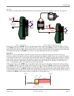
C
B
A
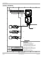
Freq. In
4-20mA
Iso Total Pluse
TR_B
TR_A
RS485 Gnd
Setpoint 1
Setpoint 2
Gnd
+
–
+
–
+
–
Total Reset
OC Total Pluse
Signal Gnd
+ –
KB/Display
J1
TB1
JP1
JP2
JP3
P2
Input
Total P
ulse
Sig
nal
P1
Mag
Pulse
Iso
OC
Low
High
2
1 2
1
A
B
C
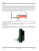
5 0 in (127 0 mm)
4 5 in (114 3 mm)
2 6 in (66 0 mm)
TROUBLESHOOTING GUIDE
Trouble
Remedy
No LCD
Display
Battery
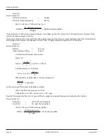
Check battery voltage Should be 3 6 V DC If the input is 3 4V DC or lower, replace the battery
Loop
power
Check 4…20 mA input Voltage must be within the minimum and maximum supply voltage and
capable of supplying enough current to run the display The input voltage is checked “across” or
in parallel with the 4…20 mA terminals and current is checked with the ammeter in series with
the 4…20 mA output
No Rate or Total
Displayed
Check connection from meter's transmitter to display input terminals
Check turbine meter rotor for debris Rotor should spin freely
Check programming of flow monitor
Flow Rate Display
Interprets Reading
Constantly
This is usually an indication of external noise Keep all AC wires separate from DC wires
Check for large motors close to the meter pickup
Check for radio antenna in close proximity
Flow Rate Indication
Erratic
This usually indicates a weak signal Replace pickup and/or check all connections
Check for correct factor
Check that the ILR transmitters meter size selection switch is set to the correct size
Model Numbers
DSY-PM-00028-EN-02
Page 31
February 2017
Summary of Contents for ER-500
Page 1: ...Display ER 500 Advanced DSY PM 00028 EN 02 February 2017 Programming Manual...
Page 2: ...ER 500 Flow Monitor Page ii February 2017 DSY PM 00028 EN 02...
Page 4: ...ER 500 Flow Monitor Page iv February 2017 DSY PM 00028 EN 02...
Page 34: ...Display ER 500 Advanced INTENTIONAL BLANK PAGE DSY PM 00028 EN 02 Page 34 February 2017...
Page 35: ...Programming Manual INTENTIONAL BLANK PAGE DSY PM 00028 EN 02 Page 35 February 2017...


