background image

Commissioning

Seite 16

December 2019

AC_F001_IA_02_2243

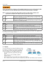
5.  Press the SELECT key, to make the 

required selection.

• 

The PROG indicator blinks 

continuously.

• 

You can select the required 

engineering unit.

Press the SELECT key as many times as 

applicable.

6.  Short and simultaneously, press the 

SELECT and CLEAR key to confirm the 

selection.

• 

The PROG indicator goes off.

• 

The selection is saved.

• 

The display shows the selected 

engineering unit.

If you do not press the SELECT and CLEAR 

key short and simultaneously to confirm, 

your selection is not saved.

7.  Press the SELECT key, to find the 

submenu: TIME.

• 

The SETUP indicator stays on 

continuously.

• 

The submenu shows: TIME.

You can select: /sec; /min; /hour; /day.

8.  Short and simultaneously, press the 

SELECT and CLEAR key to access the 

submenu: TIME.

• 

The PROG indicator blinks 

continuously.

If you wait too long, the program mode 

goes off and changes are not saved, this is 

normal behavior.

9.  Press the SELECT key, to make the 

required selection.

• 

The PROG indicator blinks 

continuously.

• 

You can select the required time unit 

for the flow rate calculation.

Press the SELECT key as many times as 

applicable.

Note that the flow rate is given in  

engineering unit/time unit,  

e.g. liters/minute (l/min).

10.  Short and simultaneously, press the 

SELECT and CLEAR key to confirm the 

selection.

• 

The PROG indicator goes off.

• 

The selection is saved.

• 

The display shows the selected amount 

of decimals.

If you do not press the SELECT and CLEAR 

key short and simultaneously to confirm, 

your selection is not saved.

11.  Press the SELECT key, to find the 

submenu: DECS.

• 

The SETUP indicator stays on 

continuously.

• 

The submenu shows: DECS.

You can select: 0; 0.1; 0.02; 0.003.

12.  Short and simultaneously, press the 

SELECT and CLEAR key to access the 

submenu: DECS.

• 

The PROG indicator blinks 

continuously.

If you wait too long, the program mode 

goes off and changes are not saved, this is 

normal behavior.

13.  Press the SELECT key, to make the 

required selection.

• 

The PROG indicator blinks 

continuously.

• 

You can select the required amount of 

decimals for the engineering unit.

Press the SELECT key as many times as 

applicable.

14.  Short and simultaneously, press the 

SELECT and CLEAR key to confirm the 

selection.

• 

The PROG indicator goes off.

• 

The selection is saved.

• 

The display shows the selected amount 

of decimals.

If you do not press the SELECT and CLEAR 

key short and simultaneously to confirm, 

your selection is not saved.
15.  Press the SELECT key, to find the 

submenu: K-F.

• 

The SETUP indicator stays on 

continuously.

• 

The submenu shows: K-F.

You can select: 0.000010 - 9999999.

Note that de K-Factor setting for the total 

and the flow rate are different.

16.  Short and simultaneously, press the 

SELECT and CLEAR key to access the 

submenu: K-F.

• 

The PROG indicator blinks 

continuously.

If you wait too long, the program mode 

goes off and changes are not saved, this is 

normal behavior.

17.  Use the SELECT key to increase the 

digit. Use the CLEAR key to go to the 

next number.

• 

The PROG indicator blinks 

continuously.

• 

You can select the required K-Factor.

The 0 (zero) in front of the number will not 

show when the setting is saved.

Also set the decimal numbers. The decimal 

separator is set in the next step.

18.  Short and simultaneously, press the 

SELECT and CLEAR key to confirm the 

selection.

• 

The PROG indicator goes off.

• 

The selection is saved.

• 

The display shows the selected 

K-Factor.

If you do not press the SELECT and CLEAR 

key short and simultaneously to confirm, 

your selection is not saved.
Summary of Contents for F001

Page 1: ...AC_F001_IA_02_2243 December 2019 Installation Manual F001 Basic Flow rate Indicator Totalizer with analog and pulse signal outputs...

Page 2: ...F001 Basic Flow rate Indicator Totalizer with analog and pulse signal outputs Seite II December 2019 AC_F001_IA_02_2243...

Page 3: ...Electrical installation General 8 4 2 1 Preparation 8 4 3 Electrical installation Coil 9 4 3 1 Electrical connections Coil 9 4 3 2 Configuration Coil 9 4 4 Electrical installation Reed 10 4 4 1 Electr...

Page 4: ...ow rate Indicator Totalizer with analog and pulse signal outputs Seite IV December 2019 AC_F001_IA_02_2243 6 Technical specifications 19 7 Default and customized settings 21 7 1 Default and customized...

Page 5: ...e to that unit or data stored within it Protection class The device has protection class IP 65 and needs to be protected against dripping water water oils etc Setup operation Adjust only those control...

Page 6: ...al and the accumulated total of a meidum that passes a sensor For details refer to the chapter Technical specifications 2 2 2 UNINTENDED USE A hazardous situation may occur if the F001 is not used for...

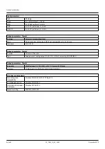
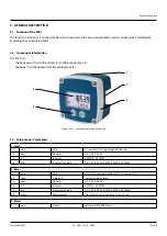
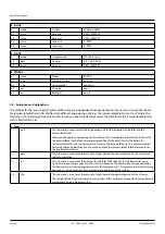
Page 7: ...2 3 4 5 Figure 1 F001 Component information typical 3 3 Setup menu Parameters 1 Total 1 1 unit Unit no unit L m kg lb gal USGAL bb 1 2 decs Decimals 0 0 1 0 02 0 003 1 3 k f K Factor 0 000010 9999999...

Page 8: ...e indication of the total and the accumulated total When you change the engineering unit for total you must recalculate and enter the K Factor for the accumulated total When you recalculate and enter...

Page 9: ...cation 2 4 k f This submenu is used to set the K Factor for the flow rate With the K Factor the flow meter pulse signals are converted to a quantity The K Factor is based on the number of pulses gener...

Page 10: ...d to the total to generate a pulse In other words the quantity that represents one pulse For support and maintenance it is important to have information about the characteristics of the F001 Your supp...

Page 11: ...F001 is installed free from excessive vibrations the F001is protected against severe weather conditions WARNING ONLY QUALIFIED AND WELL TRAINED PERSONS WHO ARE FAMILIAR WITH THE MECHANICAL INSTALLATIO...

Page 12: ...2 Electrical installation General WARNING ONLY QUALIFIED AND WELL TRAINED PERSONS WHO ARE FAMILIAR WITH THE ELECTRICAL INSTALLATION AND THE SERVICE PROCEDURES AND WHO OBEY THE SPECIFIC REGULATIONS AND...

Page 13: ...cator stays on continuously The main menu shows METER Press the CLEAR key as many times as applicable 3 Press the SELECT key to find the submenu SIGN The SETUP indicator stays on continuously The subm...

Page 14: ...icator stays on continuously The main menu shows METER Press the CLEAR key as many times as applicable 3 Press the SELECT key to find the submenu SIGN The SETUP indicator stays on continuously The sub...

Page 15: ...enu METER The SETUP indicator stays on continuously The main menu shows METER Press the CLEAR key as many times as applicable 3 Press the SELECT key to find the submenu SIGN The SETUP indicator stays...

Page 16: ...cator stays on continuously The main menu shows METER Press the CLEAR key as many times as applicable 3 Press the SELECT key to find the submenu SIGN The SETUP indicator stays on continuously The subm...

Page 17: ...dicator stays on continuously The main menu shows METER Press the CLEAR key as many times as applicable 3 Press the SELECT key to find the submenu SIGN The SETUP indicator stays on continuously The su...

Page 18: ...press the SELECT and CLEAR key to confirm the selection The PROG indicator goes off The selection is saved The display shows the selected engineering unit If you do not press the SELECT and CLEAR key...

Page 19: ...imes as applicable 17 Short and simultaneously press the SELECT and CLEAR key to confirm the selection The PROG indicator goes off The selection is saved The display shows the selected amount of decim...

Page 20: ...CS You can select 0 0 1 0 02 0 003 12 Short and simultaneously press the SELECT and CLEAR key to access the submenu DECS The PROG indicator blinks continuously If you wait too long the program mode go...

Page 21: ...rom the number of pulses which have passed during a set period of time 24 Short and simultaneously press the SELECT and CLEAR key to access the submenu MEAS The PROG indicator blinks continuously If y...

Page 22: ...this is normal behavior 5 Use the SELECT key to increase the digit Use the CLEAR key to go to the next number The PROG indicator blinks continuously You can set the required pin code The pin code 000...

Page 23: ...allowed Ambient conditions Operation Temperature 4 F to 176 F 20 C to 80 C Humidity relative 90 no condensation allowed Power requirements External power supply 10 30 V DC Consumption max 625 mW The e...

Page 24: ...DC max Frequency 5 Hz 100 Hz Output parameters Digital Function To transmit flow rate Type Loop powered analog output 12 30 V DC 3 22 mA according NAMUR NE45 Output parameters Digital Loop data Lifto...

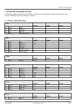
Page 25: ...Decimals 0 1 3 k f K Factor 1 1 4 kf d K Factor Decimals 0 2 Rate Default Custom Custom 2 1 unit Unit L 2 2 time Time unit min 2 3 decs Decimals 0 2 4 k f K Factor 1 2 5 kf d K Factor Decimals 0 2 6 m...

Page 26: ...Default and customized settings Seite 22 December 2019 AC_F001_IA_02_2243 6 2 v no Software version nn nn nn 6 3 s no Serial nr nnnnnnn 6 4 pin Pin code 0000 6 5 bl Backlight on...

Page 27: ...December 2019 Seite 23 AC_F001_IA_02_2243...

Page 28: ...Milwaukee WI 53224 9536 800 876 3837 414 355 0400 M xico Badger Meter de las Americas S A de C V Pedro Luis Ogaz n N 32 Esq Angelina N 24 Colonia Guadalupe Inn CP 01050 M xico DF M xico 52 55 5662 08...

Reviews: