background image

Page 53

4-11

Installation & Operation Manual

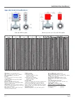
Appendix: Detector Specifications

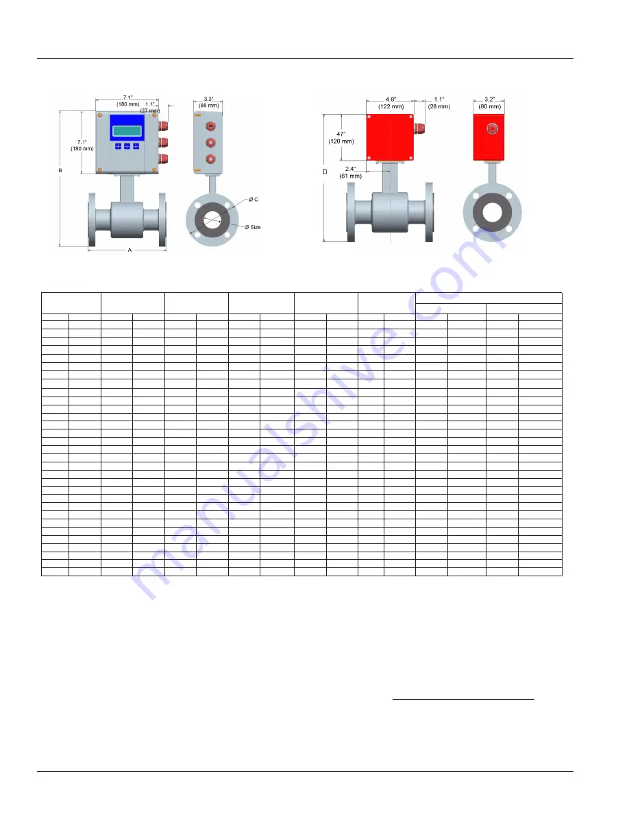
Meter with M-2000


amplifier

Meter with junction box for remote M-2000 amplifier

Size

A

B

C

D

Est. Weight 

with M-2000

Flow Range

LPM

GPM

inch

mm

inch 

mm

inch

mm

inch

mm

inch

mm

lbs

kg

min

max

min

max

1/4

6

6.7

170

14.0

356

3.5

89

11.4

288

10

4.5

0.063

20

0.02

5

5/16

8

6.7

170

14.0

356

3.5

89

11.4

288

10

4.5

0.114

34

0.03

9

3/8

10

6.7

170

14.0

356

3.5

89

11.4

288

10

4.5

0.177

53

0.05

14

1/2

15

6.7

170

14.0

356

3.5

89

11.4

288

10

4.5

0.416

125

0.11

33

3/4

20

6.7

170

14.2

361

3.9

99

11.5

293

13

5.5

0.75

225

0.2

59

1

25

8.9

225

14.4

366

4.3

108

11.7

298

18

8.0

1.20

350

0.3

93

1 1/4

32

8.9

225

15.2

386

4.6

117

12.5

318

20

9.0

2.00

575

0.5

152

1 1/2

40

8.9

225

15.4

390

5.0

127

12.7

322

21

9.5

3.00

900

0.8

239

2

50

8.9

225

15.9

403

6.0

152

13.2

335

26

11.5

4.70

1400

1

373

2 1/2

65

11.0

280

17.1

434

7.0

178

14.4

366

52

23.5

8

2400

2

631

3

80

11.0

280

17.3

440

7.5

191

14.7

372

54

24.5

12

3600

3

956

4

100

11.0

280

18.4

466

9.0

229

15.7

398

56

25.5

19

5600

5

1493

5

125

15.8

400

19.6

498

10.0

254

16.9

430

58

26.0

30

8800

8

2334

6

150

15.8

400

20.6

524

11.0

279

17.9

456

60

27.0

40

12700

11

3361

8

200

15.8

400

22.5

572

13.5

343

20.4

518

86

39.0

75

22600

20

5975

10

250

19.7

500

26.8

681

16.0

406

24.1

613

178

81.0

120

35300

30

9336

12

300

19.7

500

28.9

734

19.0

483

26.2

666

207

94.0

170

50800

45

13444

14

350

19.7

500

30.8

782

21.0

533

28.2

716

258

117

230

69200

60

18299

16

400

23.6

590

33.7

856

23.5

597

31.0

788

306

139

300

90400

80

23901

18

450

23.6

590

35.0

890

25.0

635

32.4

822

400

181

380

114000

100

30250

20

500

23.6

590

38.2

969

27.5

699

35.5

901

493

224

470

140000

125

37346

22

550

23.6

590

39.6

1005

29.5

749

36.9

937

523

237

570

170000

150

45188

24

600

23.6

590

42.2

1071

32.0

813

39.5

1003

552

251

680

200000

180

53778

28

700

23.6

590

46.2

1173

36.5

927

44.0

1118

648

294

920

275000

240

73100

30

750

31.5

800

48.3

1228

39.0

984

45.7

1161

702

319

1060

315000

280

84000

32

800

31.5

800

52.2

1325

41.4

1015

49.5

1257

768

349

1200

361000

320

95600

36

900

31.5

800

55.3

1405

46.0

1168

54.1

1374

848

385

1500

457000

400

121000

40

1000

31.5

800

60.0

1525

50.2

1230

57.4

1457

922

419

1900

565000

500

149300

42

1050

36.0

914

66.0

1675

53.0

1346

63.4

1610

1198

499

2100

620000

550

164600

48

1200

39.4

1000

69.9

1775

59.4

1455

67.2

1707

1208

549

2700

814000

720

215100

54

1400

39.4

1000

78.5

1995

68.4

1675

75.9

1927

1362

619

3700

1100000 980

292700

Flow Range: 

0.1 - 39.4 fps (0.03-12 m/s)

Sizes

: 1/4 inch to 54 inches (6 mm to 1400 mm)

Min. Conductivity:  

≥ 5 micromhos/cm

Accuracy:

± 0.25 percent of rate for velocities greater than  

1.64 ft/s (0.50 m/s)

± 0.004 ft/s (± 0.001 m/s) for velocities less than  

1.64 ft/s (0.50 m/s) 

Electrode Materials: 

Standard: Alloy C

Optional: 316 stainless steel, gold/platinum plated, 

tantalum, platinum/rhodium

Liner Material: 

PFA up to 3/8 inch, PTFE 1/2 inch to 

24 inches, Soft and Hard Rubber from 1 to 54 inches, 

Halar

®

 from 14 to 40 inches

NSF Listed:

 Models with hard rubber liner 4-inch 

size and up; PTFE liner - All sizes. 

Fluid Temperature: 

With Remote Amplifier: 


PFA, PTFE & Halar 311°F (155°C)


Rubber 178°F, (80°C) 

With Meter Mounted Amplifier: 


PFA, PTFE & Halar 212°F (100°C)


Rubber 178°F, (80°C)

Pressure Limits:

Maximum allowable non-shock pressure and temperature 

ratings for steel pipe flanges, according to American 

National Standard ANSI B16.5. (Example: 150-pound 

flanges, rated 285 PSI at ambient temperature.) (Example: 

300-pound flange rated 740 PSI at ambient temperature.)

Coil Power: 

Pulsed DC 

Ambient Temperature: 

-4°F to 140°F (-20°C to 60°C)

Pipe Spool Material: 

316 stainless steel

Meter Housing Material: 

Carbon steel welded

Flanges: 

Carbon steel - Standard (ANSI B16.5 Class 150 RF) 

316 stainless steel - Optional

Meter Enclosure Classification: 

NEMA 4X (IP66)

Optional: 

Submersible NEMA 6P (remote amplifier 

required)

Junction Box Enclosure Protection:

(for remote amplifier option) Powder coated die-cast 

aluminum, NEMA 4 (IP65)

Cable Entries: 

1/2-inch NPT Cord Grip

Optional Stainless Steel Grounding Rings: 

Meter Size   

Thickness (of one ring)

up through 10 inches 

.135 inch

12 to 20 inches 

.187 inch

Summary of Contents for M-series

Page 1: ...M Series Mag Meter Model M 2000 Installation Operation Manual IOM 175 03 4 11 PN 53400 190 Rev 3 IMPORTANT This manual contains important information READ AND KEEP FOR REFERENCE...

Page 2: ...Model M 2000 Mag Meter Page ii 4 11...

Page 3: ...t Pipe Requirements 10 Pipe Reducer Requirements 10 Chemical Injection Applications 11 Partially Filled Pipe Situations 11 Meter Gaskets and Grounding 13 Meter Pipeline Connection Gaskets 13 Meter Gro...

Page 4: ...e M 2000 21 Displays 21 Menu Selection Display 21 Numeric Entry Display 21 Function Buttons 22 Security 24 Setting the Administration PIN 24 Setting the Service PIN 24 Setting the User PIN 24 Entering...

Page 5: ...tromagnetic flow meter is intended for fluid metering in most industries including water wastewater food and beverage pharmaceutical and chemical The basic components of an electromagnetic flow meter...

Page 6: ...er for appropriate repairs or replacement All detectors with polytetrafluoroethylene PTFE liners are shipped with a liner protector on each end to maintain proper form of the PTFE material during ship...

Page 7: ...es Do not lift a detector with a forklift by positioning the detector body on the forks with the flanges extending beyond the lift This could dent the housing or damage the internal coil assemblies Ne...

Page 8: ...ibrations If pipes are vibrating secure the piping with appropriate pipe supports in front of and behind the meter If vibrations can t be restrained mount the amplifier in a remote location Do not ins...

Page 9: ...able glands are facing down Horizontal Placement M 2000 meters are equipped with an Empty Pipe Detection feature If an electrode mounted in the pipe is not covered by fluid for five seconds the meter...

Page 10: ...VE BUTTERFLY VALVE PUMP ELBOW TEE ANY VALVE FLOWMETER 3 x D 7 x D 2 x D D Pipe Size D Pipe Size MINIMUM PIPING REQUIREMENT STANDARD CONCENTRIC REDUCERS NO DISTANCE REQUIRED Pipe Reducer Requirements W...

Page 11: ...oo close the meter senses the two different conductivities for each liquid This will likely result in inaccurate measurements The injection method spaced bursts continuous stream of drips or liquid or...

Page 12: ...WRONG RIGHT FLOW FLOW FLOW WRONG FLOW RIGHT WRONG RIGHT FLOW FLOW FLOW WRONG FLOW RIGHT Do not install in a vertical downward position Position On Off valves on downstream side To minimize the possib...

Page 13: ...Grounding section page 14 Meter Grounding Process pipeline material can be either electrically conductive metal or not electrically conductive made of or lined with PVC fiberglass or concrete IMPORTA...

Page 14: ...ote Mount Configuration The remote mount configuration places the amplifier at a location away from the fluid flow and detector This is necessary in situations where process fluid temperature or the e...

Page 15: ...ing Observe all applicable local electrical codes Opening the M 2000 Cover The M 2000 amplifier s design lets you open the cover without completely removing it Cover is attached with display ribbon ca...

Page 16: ...not available a filtering or isolation system may be required Power wiring is the same for meter mount and remote mount amplifiers Remote Mount Installation If you are installing the M 2000 amplifier...

Page 17: ...up to 500 feet are available Junction Box Amplifier Connection No Description Wire Color Connection 11 Coil Green C1 12 Coil Yellow C2 13 Main Shield Black Red Ferrul CS 45 Electrode White E1 44 Elec...

Page 18: ...al input Digital outputs Communication Once the sensor and the amplifier have been wired wire any inputs and outputs to the M 2000 amplifier Do not connect the main power connection until you have mad...

Page 19: ...10 kHz 1 and 2 Digital Output 2 Passive max 30 VDC 100 mA Active 24 VDC 50 mA set Jumper JP2 Max Frequency 10 kHz 3 and 4 Digital Output 3 Passive Max 30 VDC 100 mA 10 kHz Solid State Relay 48 VAC 50...

Page 20: ...Page 20 4 11 Model M 2000 Mag Meter Digital Output Wiring Diagrams Digital Input Wiring Diagram...

Page 21: ...MORE ENTER Display format Example menu The top line shows the title of of the display screen Below that are two visible menu selections The bottom line provides directions for user input Typically a...

Page 22: ...the buttons will be referred to as or and or depending on the context The Enter button will be referred to as E Consider the button as the next step or scroll text up button During programming pressi...

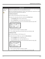
Page 23: ...ce to decrement the numeral to the value of 2 00 LOW FLOW CUTOFF of 300 000 GPM 3 00 CHG NEXT E Press LOW FLOW CUTOFF of 300 000 GPM 2 00 CHG NEXT E The E button functions as an Enter button or cursor...

Page 24: ...IN to view the Admin PIN display 3 Set the five digit PIN number to the desired value 4 Press E to save the PIN and to return to the Security menu Setting the Service PIN Users logged in with the Serv...

Page 25: ...n you call have the security code that appears in the upper right corner of the PIN Request display Follow these steps to enter your PIN in the M 2000 1 At the Main Menu press E The PIN Request displa...

Page 26: ...Second GPM Gallons Min LPM Liter Minute GPH Gallons Hour LPH Liter Hour MGD MegaGallon Day M3S Cubic Meter Sec IGS UKG Sec M3M Cubic Meter Min IGM UKG Min M3H Cubic Meter Hour IGH UKG Hour F3S Cubic...

Page 27: ...e flow is valid for both flow directions Note If the flow rate exceeds the full scale setting an error message indicates that the configured full scale range has been exceeded However the meter will c...

Page 28: ...plication requirements For example if the meter is under registering by 0 5 percent then set the scale factor to 0 5 If the meter is over registering by 0 5 percent then set the scale factor to 0 5 To...

Page 29: ...s from the Meter Setup menu 1 Select Excitation Freq to view the Excitation Frequency display 2 Position the arrow next the desired frequency 3 Press E to save the excitation frequency and return to t...

Page 30: ...low Units lets you set the unit of measure for the flow rate and full scale flow Changing the flow units parameter readjusts the full scale flow parameter For example changing from GPM to GPS would ch...

Page 31: ...larm Outputs Changes to full scale flow adjusts the thresholds for generating set point alarms Pulse Outputs Changes to full scale flow adjusts the pulse frequency and duty cycle Analog Outputs Change...

Page 32: ...e by menu Modbus RTU or digital input configured for Remote Reset Bi Directional Flow is totalized in both directions Bi directional measurements on the main display screen include T Registers forward...

Page 33: ...l be 2mA more than the configured upper range For example if the analog range is 4 to 20 mA and the alarm mode is set to HIGH then during a full scale flow alarm condition the analog output current wi...

Page 34: ...to save the new parameter and return to the Digital Output menu Pulse Width 0 ms S This parameter establishes the On duration of the transmitted pulse The configurable range is from 0 to 1000 ms Non z...

Page 35: ...ill be activated Flow rates below the threshold will activate the output alarm To change the set point minimum follow these steps from the Inputs Outputs Menu 1 Select Digital Output 1 2 3 or 4 and pr...

Page 36: ...are Type 3 Open Collector 4 Open Collector S The hardware type parameter lets you select the type of hardware used to drive the output signal either open collector or solid state relay To change the H...

Page 37: ...n Provides indication on current flow direction Inactive Reverse or No Flow Active Forward Empty Pipe Alarm Provides indication when pipe is empty To change the Function Select follow these steps from...

Page 38: ...ears the associated rollover counter PS S The batch totalizer is reset to the configured preset amount value It is reset within the menu manager remote communications or through a properly configured...

Page 39: ...ed 9600 19200 38400 To change the baud rate follow these steps from the Port A Settings menu 1 Select Baud Rate to view the Baud Rate display 2 Select one of the following baud rates 9600 19200 or 384...

Page 40: ...dcast packets address 0 processed by meter CRC Errors Number of received packets with CRC error packet is discarded Pkts Rcvd Number of packets received with an address of the configured port address...

Page 41: ...USG 1234 456 USG 1 0 USG 1 USG 12 USG 123 USG 1234 USG 10 0 USG 0 USG 10 USG 120 USG 1230 USG 100 0 USG 0 USG 0 USG 100 USG 1200 USG 1000 0 USG 0 USG 0 USG 0 USG 1000 USG To change the Unit Multiplier...

Page 42: ...red offset 5 Press E to save the option and to return to the Custom Settings menu 6 Press E to return to the Analog Calibrate menu Factory Settings Factory Set S To change the analog calibration facto...

Page 43: ...ated The filter is activated by an acceleration component of the fluid exceeding the configured limit To change the Filter Delay follow these steps from the Advanced menu 1 Select Filter Delay from th...

Page 44: ...ow setting follow these steps from the Advanced menu 1 Select Constant Flow from the Advanced menu 2 Select the desired setting 3 Press E to save the option and to return to the Advanced menu Peak Det...

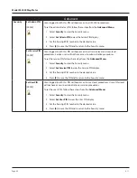
Page 45: ...e cursor on the calibration enable line and press E EMPTY PIPE CALIBRATE Volts 3 00 Cal ON E OFF Exit with Save FULL PIPE CALIBRATE Volts 1 515 Cal OFF E ON Exit with Save 4 Wait 30 seconds for voltag...

Page 46: ...ot have access to administrative procedures To set the service PIN follow these steps from the Advanced Menu 1 Select Security to view the Security menu 2 Select Set Service PIN to view the Service PI...

Page 47: ...s been observed Empty Pipe The number of times an empty pipe condition has been observed by the meter Full Scale The number of times the flow has exceeded the full scale flow setting Totalizer The num...

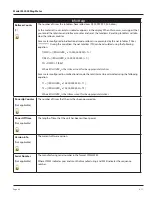
Page 48: ...000 000 000 T T REV ROLLOVERT x 10 000 000 000 T TN T FWD T REV Where ROLLOVERTx is the rollover count for the appropriate totalizer For a meter configured in unidirectional mode the totalizer can be...

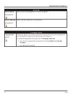
Page 49: ...s set at the factory Language Select Language Select English U The M 2000 supports one alternate language along with English This alternate language choice is set at the factory The options are Spanis...

Page 50: ...tube electrodes amplifier junction box housings and the amplifier window may need periodic cleaning depending on process fluid properties fluid flow rate and surrounding environment Clean the flow tub...

Page 51: ...nal cable Turn detector by 180 or switch terminal E1 and E2 or reprogram to bidirectional mode Check cable connections for cross wiring Verify digital input configuration Replace configuration default...

Page 52: ...er unit should be manually changed to accommodate the desired units of measure It may be necessary to set the pulses per unit to zero then change to the desired totalizer units 140 Output 3 Configurat...

Page 53: ...7 1161 702 319 1060 315000 280 84000 32 800 31 5 800 52 2 1325 41 4 1015 49 5 1257 768 349 1200 361000 320 95600 36 900 31 5 800 55 3 1405 46 0 1168 54 1 1374 848 385 1500 457000 400 121000 40 1000 31...

Page 54: ...Scalable up to 10 kHz passive open collector up to 10 kHz active switched 24 VDC Up to two outputs forward and reverse Pulse width programmable from 1 1 000 ms or 50 percent duty cycle Frequency Outpu...

Page 55: ...Page 55 4 11 Installation Operation Manual...

Page 56: ...ter Inc All rights reserved Due to continuous research product improvements and enhancements Badger Meter reserves the right to change product or system specifications without notice except to the ext...

Reviews: