Troubleshooting
Page 34/47
MID_M1000_BA_02_1802
M
10
00
-2
3
M
10
00
-24
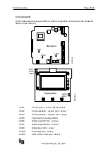
6.1 Control LED
On the board there are several LED to control the operation of the device. See below the
LEDs and the meaning
LED1
Coil loop (On = active / Off loop open)
LED2
Communication – receive (On = active)
LED3
Communication – transmit (On = active)
LED5
Flash memory activity (DISK)
LED6
Digital output #1 (On = active)
LED7
Digital output #2 (On = active)
LED8
Digital input (On = active)
LED10
Power ON (On = active)
LED13
USB, HOST mode (On = active)
LED1
LED2
LED3
LED10
Main Board
LED7
LED6
LED8
LED13
LED5
Display Board
Summary of Contents for ModMAG M1000
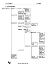
Page 46: ...Program structure Page 44 47 MID_M1000_BA_02_1802 8 Program structure ...
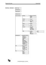
Page 47: ...Program structure Page 45 47 MID_M1000_BA_02_1802 ...
Page 50: ......
Page 51: ......


