Mount to Rotary Actuators
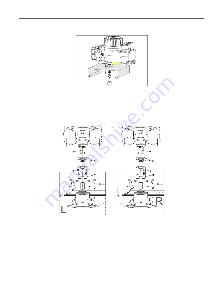
Figure 5: Mounting to rotary actuator
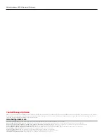
Do not tighten grub screw
4
against the thread of spindle
9
.
OTEE:
N
When the product temperature rises, the drive shaft
1
lengthens . Therefore, the rotary adaptor
3
must be mounted
with approximately 1 mm (0 .04 in .) of clearance between the drive shaft
1
and the rotary adaptor
3
. To create this
clearance, place two washers
5
on the feedback shaft stub
9
before attaching the rotary adaptor .
SRD
Rotary actuator
Figure 27: Mounting if actuator is left-rotating
SRD
Rotary actuator
Figure 28: Mounting if actuator is right-rotating
Direction
of rotation
0 --> 100 %
of actuator
shaft
1
Direction
of rotation
0 --> 100 %
of feedback
shaft
9
Figure 6: Positioner mounting
Mounting the Positioner
Page 5
May 2018
POS-QS-00502-EN-02


