background image

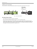
Feedback Lever for Linear Actuators

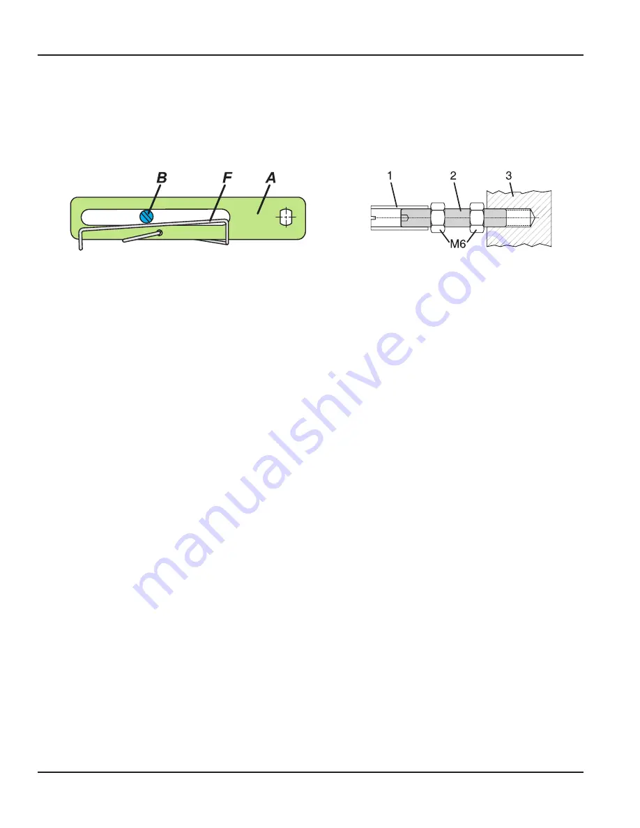
The carrier bolt 

B

 is in the slot of the feedback lever 

A

 and the compensating spring 

F

 touches the carrier bolt 

Carrier bolt B:

1 threaded sleeve 

2 Stud   

3 coupling piece 

Figure 3:  Feedback lever and carrier bolt

Mounting to Rotary Actuators

•  Do not tighten grub screw 

4

 against the thread of spindle 

9


•  When in use, the flat side of the spindle 9 must move 0 

 100% in front of the arrow 

26


•  When the product temperature rises, the drive shaft 

1

 increases in length  Therefore, the rotary adapter 

3

 must be 

mounted so there is approximately 1 mm (0 04 in ) of clearance between the drive shaft 

1

 and the rotary adapter 

3

  The 

clearance is achieved by placing an appropriate number of washers 

5

 on the feedback spindle 

9

 before attaching the 

rotary adapter  Two washers should result in a clearance of 1 mm 

Mounting to actuators

Page 6 

July 2013

POS-QS-00007-EN-02

Summary of Contents for RCV SRI990

Page 1: ...Valve Positioners SRI990 Analog Positioner POS QS 00007 EN 02 May 2018 Quick Start Guide...

Page 2: ...Valve Positioners SRI990 Analog Positioner Page ii July 2013 POS QS 00007 EN 02...

Page 3: ...means of local switches and potentiometers 9 Initial Setting 9 Configuration Direction of Rotation of Feedback Shaft 9 Setting of Zero Span and Gain 10 Setting and Start Up of position transmitter 4...

Page 4: ...Valve Positioners SRI990 Analog Positioner Page iv July 2013 POS QS 00007 EN 02...

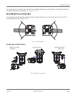
Page 5: ...operation the flat side of the spindle 9 on the back of the positioner must always point towards the arrow 26 The working angle around this position is 45 Figure 1 Actuator orientation Mounting to Lin...

Page 6: ...n use the flat side of the spindle 9 must move 0 100 in front of the arrow 26 When the product temperature rises the drive shaft 1 increases in length Therefore the rotary adapter 3 must be mounted so...

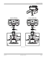
Page 7: ...Actuator left turning Actuator right turning Figure 4 Actuators Mounting to actuators Page 7 July 2013 POS QS 00007 EN 02...

Page 8: ...9234 or NAMUR Supply voltage DC 8 V SRI990 xxxV Warning For connection of micro switches please refer to MI Master Instruction and respect the safety requirements described in document EX EVE0001 Swit...

Page 9: ...t signal 4 to 20 mA and Left mounted counter clockwise rotation Configuration Direction of Rotation of Feedback Shaft Defined as direction of rotation of feedback shaft from the start to the end posit...

Page 10: ...e check zero and span settings SETTING AND STARTUP OF POSITION TRANSMITTER 4 20MA Verify the electronic connection of the position transmitter Both LED s are then light up Adjusting the Start of the M...

Page 11: ...INTENTIONAL BLANK PAGE Quick Start Guide Page 11 July 2013 POS QS 00007 EN 02...

Page 12: ...050 M xico DF M xico 52 55 5662 0882 Europe Eastern Europe Branch Office for Poland Latvia Lithuania Estonia Ukraine Belarus Badger Meter Europe ul Korfantego 6 44 193 Knur w Poland 48 32 236 8787 Eur...

Reviews: