2
TABLE OF CONTENTS
Definitions ...................................................................... 2
Installation ...................................................................... 2
Operating the Meter ....................................................... 3
Programming the Meter ................................................. 3
Operational Functions ................................................... 4
Service ........................................................................... 4
Dimensional Drawing .................................................... 7
Specifications ................................................................. 7
Parts Drawing ........................................................... 8-10
Troubleshooting ........................................................... 11
Factory Settings
Each meter is preprogrammed and calibrated at the factory.
Unless otherwise specified at the time of the order, each
meter is programmed in quarts for use with motor oil. The
meter is shipped in the Manual Mode. If you need to change
the factory settings, see page 6.
1000 psi (67 bar) Maximum Working Pressure
8 gpm (30 Lpm) Maximum Flow Rate
This Meter is designed specifically to dispense motor oils
(S.A.E. 5-50), gear oils (S.A.E. 80-240), automatic
transmission fluid, antifreeze (Ethylene Glycol) solution,
and hydraulic fluid. Other models of the EPM are designed
to dispense brake fluid or windshield wiper fluid.
SYMBOLS
This symbol is an alert to the possibility of serious injury
or death if the instructions are not followed.
This symbol is an alert to the possibility of damage to or
destruction of equipment if the instructions are not followed.
Equipment Misuse Hazard
1. This equipment is for professional use only.
2. Read all instructions, tags, and labels before
operating the equipment.
3. Use the equipment only for its intended purpose.
4. Do
NOT
modify or alter the equipment.
5. Do
NOT
leave equipment unattended while
dispensing.
6. Check equipment daily. Repair or replace worn or
damaged parts immediately.
7. Do
NOT
exceed the maximum working pressure level
of the lowest rated system component.
8. Use only extensions and nozzles that are designed
for use with this equipment.
9. Use only fluids and solvents that are compatible with
the equipment. Read all fluid and solvent
manufacturer’s warnings.
10.Tighten all fluid connections before operating this
equipment.
11.Do
NOT
stop or deflect leaks with hands, body,
gloves, or rags.
12.Do
NOT
dispense valves towards any person or any
part of the body.
13.Do
NOT
place hands or fingers over the end of or into
the dispense valve.
14.Comply with all local, state, and federal fire, electrical,
and safety regulations
15. Use of this product in a manner other than specified
in this manual may result in impaired operation or
damage to equipment.
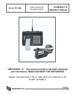
Radio Frequency Oil Management
System Overview
Badger Meter’s Radio Frequency Oil Management
System (RF-OMS) consists of an A/C powered keypad
with an integrated ticket printer and up to 48 RF
equipped meters. The product has been designed to
offer greater control over the dispensing of AFP with
significant reductions in installation costs and the
associated hardware common to most hard-wired
systems today. Dispensing information and authority is
communicated from the keypad to the meter with actual
dispensing information being communicated back to the
keypad utilizing 902-928 Mhz frequency hopping spread
spectrum radio communications. Tracking of all
dispenses, by PIN#, Work Order #, fluid type, Meter/Hose
# allows the software to compute the remaining balances
of up to 8 different tanks/fluids.
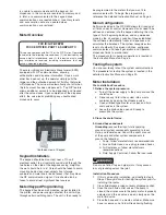
Keypad Overview
FCC ID: GIF-RFKEYPAD
FCC CERTIFIED, PART 15, SUBPART C
This device complies with Part 15 of the FCC Rules.
Operation is subject to the following two conditions: (1) this
device may not cause harmful interference, and (2) this
device must accept any interference received, including
interference that may cause undesired operation.
The keypad consists of an integrated 40-column ticket
printer, antennae for RF communications and a 16-
button keypad to enter and authorize dispensing
transactions. The Keypad also houses the electronics
that maintain the computed inventory levels via
deliveries, dispenses and other manual transactions.
The Keypad is A/C powered and should be installed
indoors as close to the meters it will communicate with
as possible (Max 300 feet) but yet secured from abuse
and environment issues. Reference the keypad
installation instructions for a list of materials that may
significantly impact RF range. Software in the keypad
recognizes two levels of authority: Supervisor and
Operator. The Supervisors Personal Identification
Number (PIN) allows for system initialization,
configuration, communication diagnostics and report
generation. The operator pin authorizes and records all
dispenses.
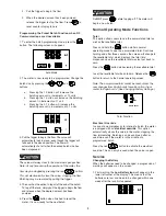
If RF Communications from the keypad to the meter are
unavailable (temporary obstruction, damage to the
keypad, power outage, etc) the meter may be
programmed to dispense in the manual mode by
entering a code via the buttons on the meter. In this
mode, the meter will only dispense after verifying that it


