Page 14
For technical questions, please call 1-800-444-3353.
ATV Winch
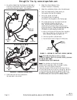
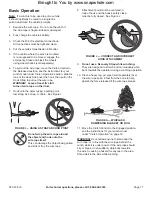
3. Route the Cables from the Solenoid to the battery
and from the Solenoid to the Winch, following the
precautions discussed earlier. See Figure E.
odel 68146
Circuit
Breaker
Solenoid
Box
Winch
Black
Black
Green
Black
Red
Red
Red
(to ignition)
odel 68145 and 68144
Red
(to ignition)
Circuit
Breaker
Solenoid
Box
Winch
Black
Blue
Black
Black
White
Green
Red
Red
Yellow
Red
FIGURE E — WIRING CONNECTIONS
4. Attach the wires from the solenoid to
the terminals on the Winch.
5. Attach the Circuit Breaker to the
Positive Terminal on the battery.
6. Attach the red Battery Cable to the Circuit Breaker.
7. Attach the black Battery Cable directly to
the negative terminal of the battery.
8. Wire in the Switch Controller
(and Socket Lead, if equipped)
according to the diagrams on the facing page.
9. The cable leading from the Switch Controller
has a red wire extending out from its
side. Connect this to an ignition circuit
(switched by the vehicle′s key) to help prevent
accidental starting.
The winch will not operate
if that wire is not properly connected.
a. Use a circuit tester to find a wire that energizes
when the vehicle′s key is turned to on, and
turns off when the key is turned to off.
b. That is an ignition controlled wire.
c. Connect wire shown in Figure F to that wire.
FIGURE F — WIRING TO VEHICLE′S KEYED IGNITION
Red
(to ignition)
Switch
Controller
Note: If not attaching the winch to a vehicle,
attach the ignition wire to the positive battery terminal.
IF THIS IS NOT DONE,
THE WINCH WILL NOT OPERATE.
Note:
The attachment of the Motor Cables
determines the operation of the Controller’s button.
After the unit is mounted and powered,
check the direction of the Power In and Power Out on
the Controller button. If you wish to change the direction
on the Controller, disconnect the Battery Cables from
the battery, switch the Motor Cable connections on the
Motor Assembly, then reconnect the Battery Cables.
REV 10l
Brought to You by www.snapwhole.com


