background image

Page 7

For technical questions, please call 1-888-866-5797.

Item 56385 


SAF

eT

y

O

Pe

RA

Ti

O

n

M

A

in

Ten

A

n

C

e

Se

Tu

P

Mounting the Winch

1.  Make sure the Winch will fit the chosen mounting 

area.  If relocating the Control Box is necessary 

or desired, perform the removal and installation 

of cables to the Winch before mounting.  Refer 

to 

Relocating the Control Box

 on page 8.

2.  The mounting plate must be rated to 

at least the Winch’s capacity.

3.  Align the Winch perpendicular to center line of 

the vehicle at the desired location, and mark the 

locations of the winch base holes.  Compare the 

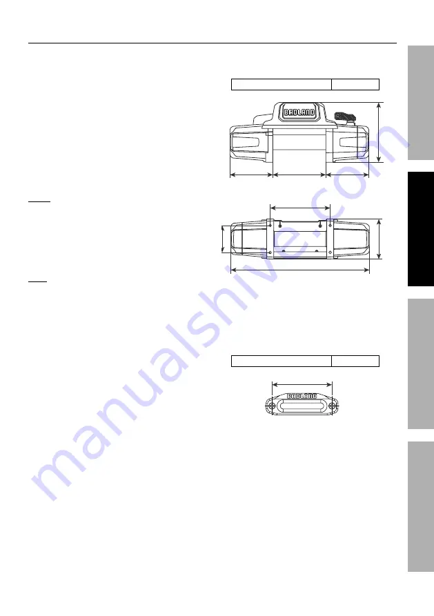
dimensions of the marked holes to Figure A.

4.  Before drilling, verify that the installation 

surface has no hidden components or 

structural pieces that will be damaged.

nOTe:  

This Winch can generate extreme 

forces.  Select a location that can withstand the 

rated capacity without damage or weakening.  

Steel reinforcement plates may be needed or a 

certified welder may need to weld on additional 

bracing depending on the mounting location.

5.  Drill holes appropriate for the hardware 

at the marked locations.

note:

  Depending on the vehicle application, it may 

be beneficial to install the wiring before mounting 

the Winch.  Check all terminal access and plan 

wiring routes before mounting the Winch.

6.  Install the Winch using hardware specified 

on the specification chart.  Tighten fasteners 

to the following torque values:

Winch mounting fasteners

30 –33 ft-lb

8.82 in. / 224 mm

7.2 in. / 183 mm

7.2 in. / 183 mm

10.0 in. / 254 mm

10 in. / 254 mm

23.2 in. / 590 mm

6.50 in. / 165.0  mm

4.49 in. /  114 mm

Figure A:  Winch Dimensions

7.  Mount the Fairlead centered on the Winch 

to guide the Rope onto the Winch drum.

8.  Install the Fairlead using hardware specified  

on the specification chart.  Tighten fasteners 

to the following torque values:

Fairlead mounting fasteners

53 – 57 ft-lb

10 in. / 254 mm

Figure B:  Fairlead Mounting Dimensions

Summary of Contents for APEX 12000

Page 1: ...rence 22h When unpacking make sure that the product is intact and undamaged If any parts are missing or broken please call 1 888 866 5797 as soon as possible Copyright 2022 by Harbor Freight Tools All rights reserved No portion of this manual or any artwork contained herein may be reproduced in any shape or form without the express written consent of Harbor Freight Tools Diagrams within this manua...

Page 2: ... 8 Replaceable with Spring loaded Safety Latch Fairlead Aluminum Fairlead Sound Rating 85 dB Synthetic Rope Size Type Ø0 375 x 80 Ø9 5mm x 24 4m Battery 12VDC Minimum 650 CCA Battery Cables Minimum 2 AWGx6 Mounting Bolt Pattern 10 x 4 5 254mm x 114 3 mm Mounting Hardware Winch 8x Gr8 8 M10 x 30mm Fairlead 2x Gr8 8 M12 x 40mm Overall Dimensions L x D x H 23 1 4 x 6 1 2 x 10 590 5 mm x 165 1mm x 254...

Page 3: ...n resistant leather gloves Wear ANSI approved safety glasses Cut or sever hazard Roller entanglement hazard Hot surface burn hazard Fire hazard Caustic chemical acid hazard Explosion hazard Do not loop the synthetic rope around object and hook onto itself Do not place finger s through hook Fingers may be caught and get pulled into fairlead or drum Pull hook using strap only Symbol Property or Stat...

Page 4: ...es gas tanks or any other component which could be damaged during drilling 4 Mounting location and hardware must support Winch and load 5 Use supplied power cords and synthetic rope listed in manual only Do not use thinner longer cables or link multiple cables together 6 Do not route electrical cables near sharp edges or parts that will move or become hot 7 Ventilate area well before and while wor...

Page 5: ...vice 3 Use supplied power cords synthetic rope or cables listed in manual only Do not use thinner longer cables or link multiple cables together 4 Have the Winch serviced by a qualified repair person using only identical replacement parts This will ensure that the safety of the Winch is maintained 5 Maintain labels and nameplates on the Winch These carry important safety information If unreadable ...

Page 6: ...this product What s in the Box Winch x 1 Aluminum Fairlead x 1 Hook x 1 Remote Control x 1 Rope Protecting Mat x 2 Ground Cable x 1 Disconnect Switch x 1 Remote Control Cable x 1 Red Hook Strap x 1 Control Box Baseplate x 1 Sheath red black yellow x 3 Small Black Wire Connector x 1 Small Black Wire Extension x 1 Instruction Books Manual Guide to Winching Power Cables relocation kit x 3 Extended Co...

Page 7: ...ted capacity without damage or weakening Steel reinforcement plates may be needed or a certified welder may need to weld on additional bracing depending on the mounting location 5 Drill holes appropriate for the hardware at the marked locations Note Depending on the vehicle application it may be beneficial to install the wiring before mounting the Winch Check all terminal access and plan wiring ro...

Page 8: ...lack Wire from terminal on rear of Winch Make sure the Small Black Wire that connects to the Control Box is disconnected and hanging freely Small Black Wire Ground Cable 4 Remove the Terminal Cover by unscrewing two M4x10 Screws holding it in place Remove the six Motor Terminal Nuts and three Copper Plates Retain all the hardware Motor Terminal Cover Motor Terminal Nuts Copper Plates M4x10 Screw 5...

Page 9: ...nnect three Power Cables control box relocation kit to the Control Box using remaining three Motor Terminal Nuts removed in step 4 Motor Terminal Nuts Control Box Black Red Yellow 11 Use the Small Black Wire Connector and Small Black Wire Extension to lengthen the Small Black Wire from the Control Box Reconnect the Ground Cable and Small Black Wire to the backside of the Winch motor Small Black Wi...

Page 10: ...from the Winch to the battery following the precautions discussed above Refer to Figure C Disconnect Switch Black Ground Cable Red Battery Cable 12 Cable Socket Cover Small Black Wire Figure C Wiring Connections 4 Attach the 12 2AWG Disconnect Switch Cable to the positive terminal on the battery 5 Attach the 12 2AWG Cable from the battery to either terminal on the Disconnect Switch 6 Attach the re...

Page 11: ...operly coiled under tension to be able to support a load without damage 1 Find a suitable location where the Rope can be spooled onto the Winch while anchored to a solid object Approximately 70 feet will be required Alternately a snatch block sold separately may be used to reduce the distance to 35 feet 2 Move the Clutch Handle to the Freespool position and uncoil the Synthetic Rope until 5 wraps ...

Page 12: ...nthetic Rope out Wireless Operation 1 For wireless Remote Control operation turn on the Wireless Receiver Switch on the Control Box Wireless Receiver Wireless Receiver Switch Switch Control Control Box Box 2 Press and hold the ON OFF Switch on the Remote for approximately 2 seconds until the red indicator light comes on indicating the Remote Control is ready for use IN OUT Rocker Switch ON OFF Swi...

Page 13: ...ps and general winch operating procedures If this guide is unreadable or missing contact Harbor Freight Tools for a replacement Read the ENTIRE IMPORTANT SAFETY INFORMATION section at the beginning of the Guide to Winching including all text under subheadings therein before use of this product The instructions included in the Guide to Winching are basic guidelines only and cannot cover all situati...

Page 14: ...l wiring corroded or loose terminals any other condition that may affect its safe operation Examine the Synthetic Rope Do not use the Winch if the Rope is frayed or has cut strands 2 AFTER USE wipe external surfaces of the Winch with clean cloth If the Winch is submerged during use rinse thoroughly with fresh clean water when finished 3 The Winch s internal mechanism is permanently lubricated Do n...

Page 15: ...3 Fully charge battery Run Winch with vehicle motor running 4 Replace Control Box 5 Turn ON Wireless Receiver Switch 6 Turn ON Wireless Remote 7 Turn ON Winch Disconnect Switch 8 Replace Remote batteries CR2032 quantity two 9 Check for voltage at armature port with Switch pressed If voltage is present replace motor 10 Check and tighten ground cable to Control Box 11 Replace motor Motor runs but dr...

Reviews: