background image


BaehrTec A2000 operating instructions 

English – V101 - effective 10/13 

Page 45/58 


5.4


Recycling/disposal 


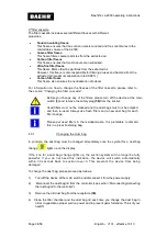
Waste devices must be disposed of as electronic waste and do not belong in the 
household waste. Please refer to the country-specific particularities for this. 
The resulting waste must be recycled or disposed of in a way that is not hazardous to 
humans or the environment. Please note the applicable national provisions here. 


The device is subject to the EC Directive 2002/96 on waste electrical and electronic 
equipment (WEEE). Therefore, we would like to point out that the device must be 
disposed of in line with the these special requirements within Europe. 

Summary of Contents for TEC A2000

Page 1: ...riggate Medical Company recommend that this appliance be sent to us for inspection every 18 MONTHS SERVICE FREQUENCY Preventative Maintenance scope dis assemble and clean vacuum motor clean and test c...

Page 2: ...er 16 4 1 1 Front view 16 4 1 2 Side view with handpiece holder 17 4 1 3 Side view with dust bag lid closed 18 4 1 4 Side view without dust bag lid and turbine protection filter open 19 4 1 5 Dust bag...

Page 3: ...on 43 5 2 Maintenance disinfection 44 5 3 Guarantee 44 5 4 Recycling disposal 45 5 5 Self help in the event of malfunctions 46 5 5 1 Changing fuses 48 5 5 2 Cleaning the handpiece button 48 5 5 3 Chan...

Page 4: ...ors air conditioning systems refrigerators or the like Please also avoid positioning near to water sources for example sinks and or chemicals Ensure an appropriately hygienic environment Place the dev...

Page 5: ...the event of lighting strike and or overvoltage the device may be damaged For this reason we also recommend installing overvoltage protection and removing the plug during a storm and or after a long...

Page 6: ...akage currents with standards Type B Before first using the device it is essential to read and follow the operating instructions Electrical electronic waste Devices with this label must be disposed of...

Page 7: ...he mains adapter is connected to earth the label can be found directly on the mains adapter 2 1 3 2 1 3 Symbols on the packaging Transport upright up in direction of arrow Protect from impacts Protect...

Page 8: ...um speed for the instrument currently in use is not exceeded In addition to the proven Easy Speed concept the BaehrTec A2000 also has a colour display which shows you additional information and allows...

Page 9: ...the event of clavi or haematoma of the subungual tissue to roughen the nail in preparation for brace correction for preparation in the event of whitlow to remove severe plate like callosities Other t...

Page 10: ...onnel must ensure that neither hair nor other loose objects such as cloths cotton wool or the like can come into the area of the rotating tools A hair net must be worn where necessary The operating pe...

Page 11: ...result in a reduced product life It is therefore important to clean and care for the device regularly and properly and to send the device regularly for service pay attention to service display or wit...

Page 12: ...lter is already inserted for you Dimensions 48 x 57 5 mm 2 x carbon filter fleece 1 filter is already inserted for you Dimensions 48 x 57 5 mm 2 x ultra fine filter fleece 1 filter is already inserted...

Page 13: ...rk with the device again please order a new power cable For the operation of your device you may only use power cables that have been approved by the manufacturer If you require a new cable please con...

Page 14: ...warm Never submerge the device in liquids and do not suck up any liquids If you suck up any cotton wool paper or the like this may cause the suction openings in the handpiece to become blocked This m...

Page 15: ...sk of injury As shown in the illustration you should avoid pulling motions during your work as this may cause the instruments to slip out Whilst working ensure that you do not apply too much pressure...

Page 16: ...speeds 6 000 40 000 rpm with the corresponding 5a 12a LEDs 13 Push button to turn the handpiece motor on off Push buttons for handpiece speed 14 and 15 1 000 rpm 16 Push button for instrument operatio...

Page 17: ...BaehrTec A2000 operating instructions English V101 effective10 13 Page 17 58 4 1 2 Side view with handpiece holder Fig 5 32 Handpiece holder...

Page 18: ...tions Page 18 58 English V101 effective 10 13 4 1 3 Side view with dust bag lid closed Fig 6 33 Dust bag lid with handle 34 Handpiece outlet 35 Screws for handpiece outlet Must only be unfastened by t...

Page 19: ...BaehrTec A2000 operating instructions English V101 effective10 13 Page 19 58 4 1 4 Side view without dust bag lid and turbine protection filter open Fig 7 37 4x magnet holder 38 Filter grille...

Page 20: ...2000 operating instructions Page 20 58 English V101 effective 10 13 4 1 5 Dust bag lid interior Fig 8 39 Receptacle for dust bags 40 Mounting bolts for magnet holder 41 Rubber seal for dust bag lid 42...

Page 21: ...the case in order that the heat created by the device can escape from the case and to avoid potential head build up 43 Filter cassette 44 Knurled screws 45 Fuse clip For microfuses 2x 3 15 A delay typ...

Page 22: ...ish V101 effective 10 13 4 1 7 Underside view Fig 10 49 Housing screws All housing screws must only be unfastened by the manufacturer 50 Housing seal As soon as the housing seal is breached or removed...

Page 23: ...ctive 10 13 Page 23 58 4 2 Description of handpiece 36 Suction hose Fig 11 52 Opening for DIN instruments with a shaft diameter of 2 35 mm for instruments with a maximum diameter of 12 mm 53 Handpiece...

Page 24: ...maximum permissible top speed of the instrument manufacturer Ensure that these are never exceeded under any circumstances as this may lead to severe injuries to the patient and to the operator In add...

Page 25: ...BaehrTec A2000 operating instructions English V101 effective 10 13 Page 25 58 4 3 Description of device connector cable Fig 13 56 Device connector 57 Cable 58 Safety plug...

Page 26: ...imum If you do not turn on the suction yourself we shall describe this in the following as deactivated suction Please be aware that this is always running even if you have not turned it on You can set...

Page 27: ...suction on Can only appear while the handpiece motor is running Therefore the following situations are possible Handpiece motor Suction ready for operation Bar graph on the display Suction Off No Tra...

Page 28: ...y function Suction level Suction level Speed of the handpiece motor Here you will be shown the rotation speed that is currently set for the handpiece motor Handpiece motor instrument rotation directio...

Page 29: ...ervice in order to prevent elaborate and costly repairs and to comply with your medical device s inspection requirements in accordance with VDE 0751 1 The service interval is actually 900 hours But as...

Page 30: ...do not be surprised therefore if the device already has some meter readings This is perfectly normal and does not mean that it is a used device For reasons of operational safety we recommend that you...

Page 31: ...ll be retained even if you turn off the device In order to save settings please set them instrument rotation speed instrument rotation direction and suction level in Work mode and hold the memory butt...

Page 32: ...y plug 58 from the socket 4 8 1 Disconnecting In order to disconnect the dust bag lid from the controller please follow these steps 1 Hold the dust bag lid from the handle and lift it from the control...

Page 33: ...t excessive germ build up Think of your health Before we describe the process of changing the filter we would like to give you a brief insight into the filter system used in the BaehrTec A2000 1 st fi...

Page 34: ...remove the safety plug 58 from the socket Used filters must not be cleaned and the dust bags must not be emptied and then re used Always use fresh filters and a new dust bag for each filter change Pl...

Page 35: ...otection filter and all other filters must be replaced immediately if you have been working with your BaehrTec A2000 without a dust bag if you forgot or if a dust bag has burst To change the turbine p...

Page 36: ...You should also change the turbine protection filter and the other filters if you believe that the symbol for a dust bag change has lit up too early after successfully changing the dust bag In princi...

Page 37: ...ntroller using Baehr cloths Art No 11000 4 Remove the knurled screws from the filter cassette and open it by pulling the filter cassette grille from the base of the filter cassette Pull the filter cas...

Page 38: ...n the order indicated on the outside of the filter cassette and then put them back into the filter cassette Next put the filter cassette grille back into the base of the filter cassette Fig 19 6 Chang...

Page 39: ...st bag lid to the controller If the dust bag is missing you must insert a new dust bag before working with the device see section Changing the dust bag Now connect the dust bag lid back onto the contr...

Page 40: ...currently want to work with The instrument heads depicted max diameter and the associated speed should help you to quickly and safely find the permitted maximum speed for your instruments The permitt...

Page 41: ...ment be sure to follow the manufacturer s instructions on the permitted maximum speed The maximum speed specified there must not be exceeded under any circumstances This poses a danger of injury and t...

Page 42: ...is prevents the device from being damaged For information on how to change the dust bag please refer to the section Changing the dust bag We are convinced that after just a short time you will be able...

Page 43: ...ever spill liquids on the foot pedal or use the foot pedal on wet surfaces If fluids should get into the foot pedal do not use it under any circumstances Please send the foot pedal in for service Ther...

Page 44: ...rder to prevent excessive germ build up Think of your health 5 3 Guarantee The guarantee shall last 24 months There is no liability for defects and their consequences which are caused by natural wear...

Page 45: ...ecific particularities for this The resulting waste must be recycled or disposed of in a way that is not hazardous to humans or the environment Please note the applicable national provisions here The...

Page 46: ...t panel and clean the handpiece It is essential that the device is turned off and disconnected from the mains beforehand Change dust bag Change turbine protection filter Change filter in cassette Low...

Page 47: ...p and the instruments are clean Reduce pressure Avoid pulling motions Suction turbine switches to suction level 3 during operation Dust bag turbine protection filter and filter cassette are full devic...

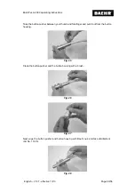
Page 48: ...ver to open the fuse compartment on the device socket Fig 22 Replace the microfuses in the compartment Now push the compartment back into the device socket Make sure that the compartment snaps into pl...

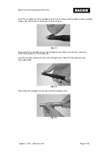
Page 49: ...ke the button pusher between your thumb and forefinger and pull it out from the button housing Fig 25 Clean the button pusher and the button housing with a brush Fig 26 Fig 27 Next wipe the button pus...

Page 50: ...on pusher with your finger Fig 30 5 5 3 Changing the dampers for the handpiece case If you notice that the handpiece motor no longer sits comfortably in the handpiece case this means that the dampers...

Page 51: ...ossibly using a pair of tweezers and dispose of these properly Fig 33 Now reinsert the new dampers for the handpiece case Make sure that you insert the three black dampers in the middle row Insert the...

Page 52: ...tion level 1 with filter and dust bag 40 m bar 10 Max vacuum suction level 2 with filter and dust bag 55 m bar 10 Max vacuum suction level 2 with filter and dust bag 62 m bar 10 Max vacuum suction lev...

Page 53: ...e 8 kV air discharge 6 kV Contact discharge 8 kV air discharge Floors should be made from wood or concrete or covered with ceramic tiles If the floor is covered with synthetic material the relative hu...

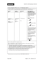
Page 54: ...an investigation on site a the field strengths of fixed transmitters is lower than the COMPLIANCE LEVELb at all frequencies Interference is possible in the vicinity of devices marked with the followi...

Page 55: ...tion belonging to the respective column where P is the nominal power of the transmitter in watts W according to the indication of the transmitter manufacturer NOTE 1 To calculate the recommended prote...

Page 56: ...BaehrTec A2000 operating instructions Page 56 58 English V101 effective 10 13 Notes...

Page 57: ...BaehrTec A2000 operating instructions English V101 effective 10 13 Page 57 58 Notes...

Page 58: ......

Page 59: ......

Page 60: ...Page 58 58 English V101 effective 10 13 Gustav Baehr GmbH Max Eyth Str 39 D 71332 Waiblingen Tel 07151 95 90 20 Fax 07151 1 84 44 www baehrshop de...

Reviews:

Related manuals for TEC A2000