background image

BA_373-E45_05_DEF_MJ_21

19

31 | 

36

W. Baelz & Sohn GmbH & Co.

 · Koepffstrasse 5 · 74076 Heilbronn · Germany · 

www.baelz.de             Seite | Page  

Motorized Linear Actuator   


    baelz 373-E45

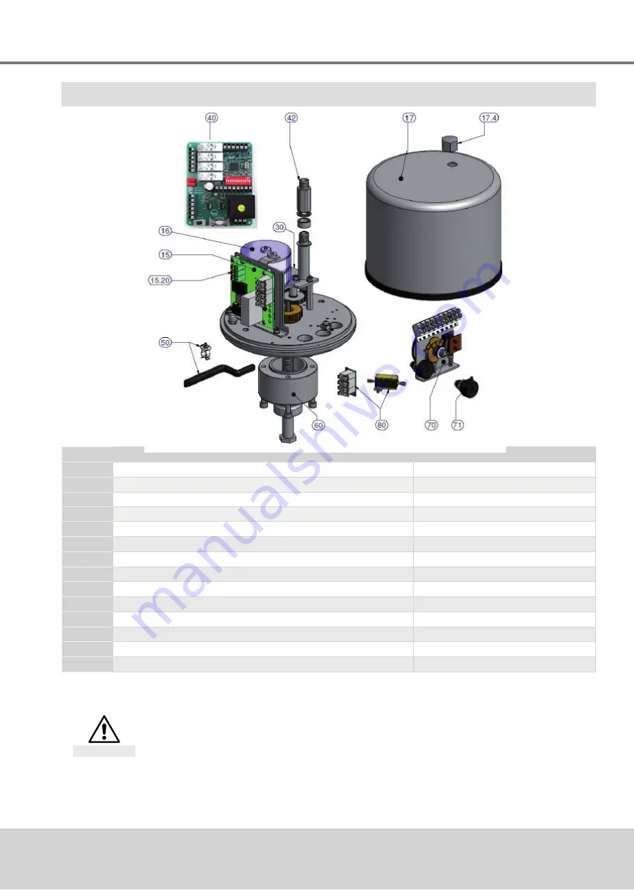
10.  SPARE PARTS

Part no. Description

Remarks

15

Mounting plate (complete)

15.20

Circuit board, including motor capacitor (complete)

16

Motor (complete)

17

Cover (complete)

(F1653882 and above: new version)

17.4

Cap nut

30

Mounting plate

40

Digital positioner 7020A

41

Fitting material for digital positioner 7020A

42

Extension

50

Crank handle (complete)

60

Flange, complete with connecting rod

70

Potentiometer assembly including 2 limit switches (complete) 

(F1653882 and above: new version)

71

Potentiometer (complete)

(F1653882 and above: new version)

80

Heating element (complete)

When ordering accessories or spare parts, please note the specifications on the actuator 

nameplate for essential information regarding actuator and power supply criteria.


Risk of damage to actuator due to incorrect or defective spare parts!

Attention

All spare parts must comply with the technical requirements as stated by the manufacturer.


● Use only original spare parts!

Summary of Contents for BA 373-E45

Page 1: ...5 74076 Heilbronn Germany www baelz de Seite Page BA_373 E45_05_DEF_MJ_2119 Operating Instructions BA 373 E45 Motorized Linear Actuator baelz 373 E45 Technical specifications subject to change without...

Page 2: ...otorized linear actuator 6 2 2 Technical Specifications 6 2 4 Accessories and options 7 2 3 Type name 7 2 5 Operating conditions 7 3 TRANSPORT AND STORAGE 7 4 ASSEMBLY 8 4 1 Fitting position 8 4 2 Ass...

Page 3: ...2 5 3 point control with a continuous output signal 20 8 3 Wiring diagrams and allocation of connection terminals 20 8 3 1 Wiring diagram 20 8 3 2 Allocation of connection terminals 21 8 4 Configurati...

Page 4: ...dentification complies with the nameplate of the linear actuators before starting any activities The actual technical specifications of the linear actuators and the power supply requirements are the s...

Page 5: ...ny way 1 4 Before starting work Before carrying out any work check whether the types specified here correspond to the information on the name plate of the actuator baelz 373 E45 1 5 During operation S...

Page 6: ...ower consumption 230 V VA 11 Nominal current 230 V A 0 045 Type of motor synchronous motor syn Motor protection stall proof motor B Maximum stroke mm 44 Supply voltage 2 24 V 115 V 230 V 50 60 Hz 10 O...

Page 7: ...case of extreme variations in ambient temperature and high humidity levels installation of a heating resistor is recommended to minimise condensation in the actuator Actuator covers with suppression o...

Page 8: ...mage if no valve is fitted to actuator Caution Caution If the linear actuator is operated without a valve the missing stop may cause damage to the actuator The actuator must therefore never be operate...

Page 9: ...e and actuator match The linear actuator is supplied with the spindle retracted A slight adjustment for fitting of the coupling can be carried out by turning the spindle The following dimensions must...

Page 10: ...le spindle nut is driven by an electric motor via a gearbox This converts the rotary movement into a linear movement Load dependent limit switches dictate the end positions 4 3 1 Manual adjustment Man...

Page 11: ...ower supply For wiring and connection observe the regulations for the construction of electric power installations and the regulations of the local energy supplier Check compliance of the supply volta...

Page 12: ...rection of rotation is wrong switch off immediately Check wiring jumpers Repeat the test run If the direction of travel is set incorrectly damage to actuator and valve is imminent as the limit switche...

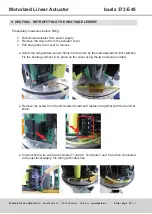
Page 13: ...he distance sleeve 4 onto the threaded end of the connecting rod and tighten Place the laminate washer 2 over the threaded end onto the self locking nut Insert the position detector for the potentiome...

Page 14: ...oke 44 mm note that for reverse mode the potentiometer must be turned to the new zero point mechanical stop opposite For this adjustment the actuator spindle must be in the correct end position Normal...

Page 15: ...020A DIGITAL POSITIONER Disconnect actuator from power supply before starting work Danger These instructions apply given that the potentiometer assembly has been correctly fitted as described in secti...

Page 16: ...373 E45 Before fitting the adaptor panel the nameplate must be stuck to the underside If the digital positioner board ist replaced this nameplate must also be changed Place the 4 click fit spacer con...

Page 17: ...anel on the bracket so that the countersunk hole and the hole in the bracket are aligned Insert the plastic screws and fit and tighten the nuts on the underside of the bracket Fit the spacer sleeve on...

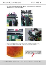
Page 18: ...ar Actuator baelz 373 E45 Wire up the digital positioner board with the motor and the potentiometer according to the wiring diagram 7020A Fig 9 page 21 Stick the wiring diagram to the inside of the ac...

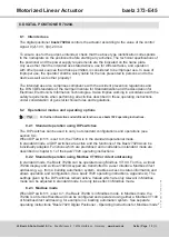
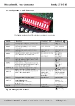
Page 19: ...onal modes and operating options For further information and additional functions see baelz 7020 operating instructions 8 2 1 Standard operation using DIP switches The DIP switches can be used to carr...

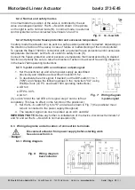
Page 20: ...o account See wiring diagrams in the baelz 7020 operating instructions 8 2 5 3 point control with a continuous output signal 1 Set the positioner up and wire to power supply as described previously an...

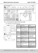
Page 21: ...control the N S switch must be set to S safety mode 20 22 Digital input for a switch used to select between two conditions e g open closed or summer winter 23 24 25 26 Analogue output position indica...

Page 22: ...spindle extended valve closed DIP 5 Current position of the actuator is saved as additional switching position 2EZ 1 See wiring diagram page 21 from 0 to 1 save 2EZ 1 2 DIP 6 Current position of the a...

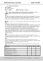
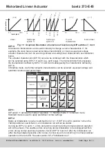
Page 23: ...run whether or not the unit was already initialized before starting the current initialization run The direction of operation must not be confused with heating cooling Heating in standard mode is carr...

Page 24: ...t to 1 errors and alarms occurring during normal positioner operation will not be shown This enables errors occurring during initialization to be distinguished from errors during normal positioner ope...

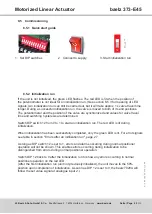
Page 25: ...zed and values for valve travel time and switching hysteresis are determined Switch DIP switch 12 from 0 to 1 to start an initialization run The red LED is lit during initialization When initializatio...

Page 26: ...un Initialization still possible If the red LED is flickering the position of the potentiometer is at the edge of the optimal range and therefore OK 5 green and red flashing Error during initializatio...

Page 27: ...ormal positioner operation Setting DIP switch 12 from 1 back to 0 permits the red LED to show any normal operational errors instead of initialization errors which may have occured Error code Error Cor...

Page 28: ...allocated The error codes 7 to 10 are not allocated and are reserved for additional alarms Error code Error Corrective action 1 Sensor malfunction at analogue input AI1 No signal from potentiometer C...

Page 29: ...tact load 10 V 100 mA 2 output signals Output 1 0 2 10 V min ohmic resistance 5k Output 2 0 4 20 mA max ohmic resistance 300 Factory setting 0 10 V and 0 20 mA Input signal 0 2 10V Re 63k 0 4 20mA Re...

Page 30: ...cap nut from the actuator cover 3 Pull and gently turn cover to remove Screw the temperature sensor firmly into the hole by the load dependent limit switches Fix the heating element in its place on th...

Page 31: ...positioner 7020A 42 Extension 50 Crank handle complete 60 Flange complete with connecting rod 70 Potentiometer assembly including 2 limit switches complete F1653882 and above new version 71 Potentiome...

Page 32: ...orrectly installed 2 Check the actuator settings and the specifications on the nameplate 3 Correct the problems as specified in the checklist page 33 4 If the problem cannot be corrected contact the B...

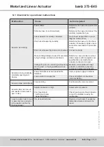
Page 33: ...ns dismantle linear actuator and return for repair Voltage drop due to connecting cables being too long and or having insufficient cross section Measure current data with linear actuator recalculate c...

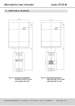
Page 34: ...6 Heilbronn Germany www baelz de Seite Page Motorized Linear Actuator baelz 373 E45 13 DIMENSIONAL DRAWINGS Fig 12 Dimensional drawing baelz E45 with S21 yoke and spindle 10 mm Fig 13 Dimensional draw...

Page 35: ...H Co Koepffstrasse 5 74076 Heilbronn Germany www baelz de Seite Page Motorized Linear Actuator baelz 373 E45 Fig 14 Dimensional drawing baelz E45 with S41 yoke and spindle 16 mm Fig 15 Dimensional dra...

Page 36: ......

Reviews: