Page 13/24
Operating Instructions
BA 7020
Technical specifications subject to change without notice
Copyright according to ISO 16016
BA_7020_00_EN_MJ_4917
6.2 Operating the postioner
Fig. 4: DIP switches
Switch
Function
Position 1 "ON"
Position 0
DIP 1
Set value input: voltage, V or current, mA?
current, mA
voltage, V
DIP 2
Set value input starting at 0 V / 0 mA or
2 V / 4 mA?
2-10 V / 4-20 mA
0-10 V / 0-20 mA
DIP 3
Analogue output starting at 0 V / 0mA or
2 V / 4 mA?
2-10 V and / or
4-20 mA
0-10 V and / or
0-20 mA
DIP 4
Direction of control action: valve closed with
drive spindle extended or retracted?
Drive spindle
retracted →
valve closed
Drive spindle
extended →
valve closed
DIP 5
Current position of the actuator is saved as
additional switching position "2EZ-1". See
wiring diagram, chapter 10.
from 0 to 1 →
save "2EZ-1"
= 2%
DIP 6
Current position of the actuator is saved
as second additional switching position
"2EZ-1". See wiring diagram, chapter 10.
from 0 to 1 →
save "2EZ-2"
= 98%
DIP 7, 8, 9
These 3 DIP switches define the function:
linear / split range / 11-point / inverted
s. Fig. 9, page 16
= linear
DIP 10
Defines valve characteristic using actuator
Actuator
characteristic inverse
equal percentage,
valve action linear
Actuator
characteristic linear,
valve action equal
percentage
DIP 11
Selects standard or Modbus mode.
Modbus mode
standard mode
DIP 12
Starts initialisation run.
Set back to 0 after initialisation
(s. chapter 7.2)
from 0 to 1 →
starts initialisation
run
N↔S
Selects normal or safety mode
position "S"
= safety mode
position "N"
= normal mode
= ex-works setting
The ex-works setting of the DIP
switches is position 0, as shown.
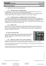
Fig. 5: N↔S switch
switches between
rormal and safety
mode.
Fig. 6: Setting the DIP switches


