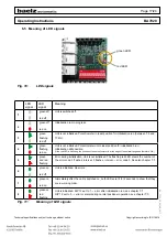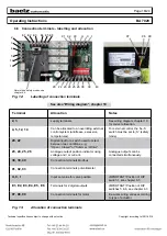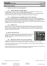
Page 15/24
Operating Instructions
BA 7020
Technical specifications subject to change without notice
Copyright according to ISO 16016
BA_7020_00_EN_MJ_4917
DIP 11:
DIP switch 11 defines the mode of operation: 1 = Modbus mode, 0 = standard mode.
Standard mode is used to apply predefined normal settings.
DIP 12:
Starts an initialisation run when switched from 0 to 1. If DIP 12 is left in position 1 when the 7020 positioner is
switched on, an initialisation run will not be startet.
As long as DIP 12 is set to 1, errors and alarms occurring during normal positioner operation will not be shown.
This enables errors occurring during initialisation to be distinguished from errors during normal positioner
operation. Switch DIP 12 back to 0 after the initialisation run (after having analysed possible error codes) to show
any errors occurring in normal positioner operation on the red LED. See also chapter 6.4 "Initialisation run".
Function
DIP 7
DIP 8
DIP 9
Linear, 1:1
0
0
0
Split range: split 50%, offset 0%
1
0
0
Split range: split 50%, offset 50%
0
1
0
Split range: split 33.3%, offset 0%
1
1
0
Split range: split 33.3%, offset 33,3%
0
0
1
Split range: split 33.3%, offset 66,6%1
1
0
1
11-point characteristic
0
1
1
Inverted: 0 becomes 100 and 100 becomes 0%
1
1
1
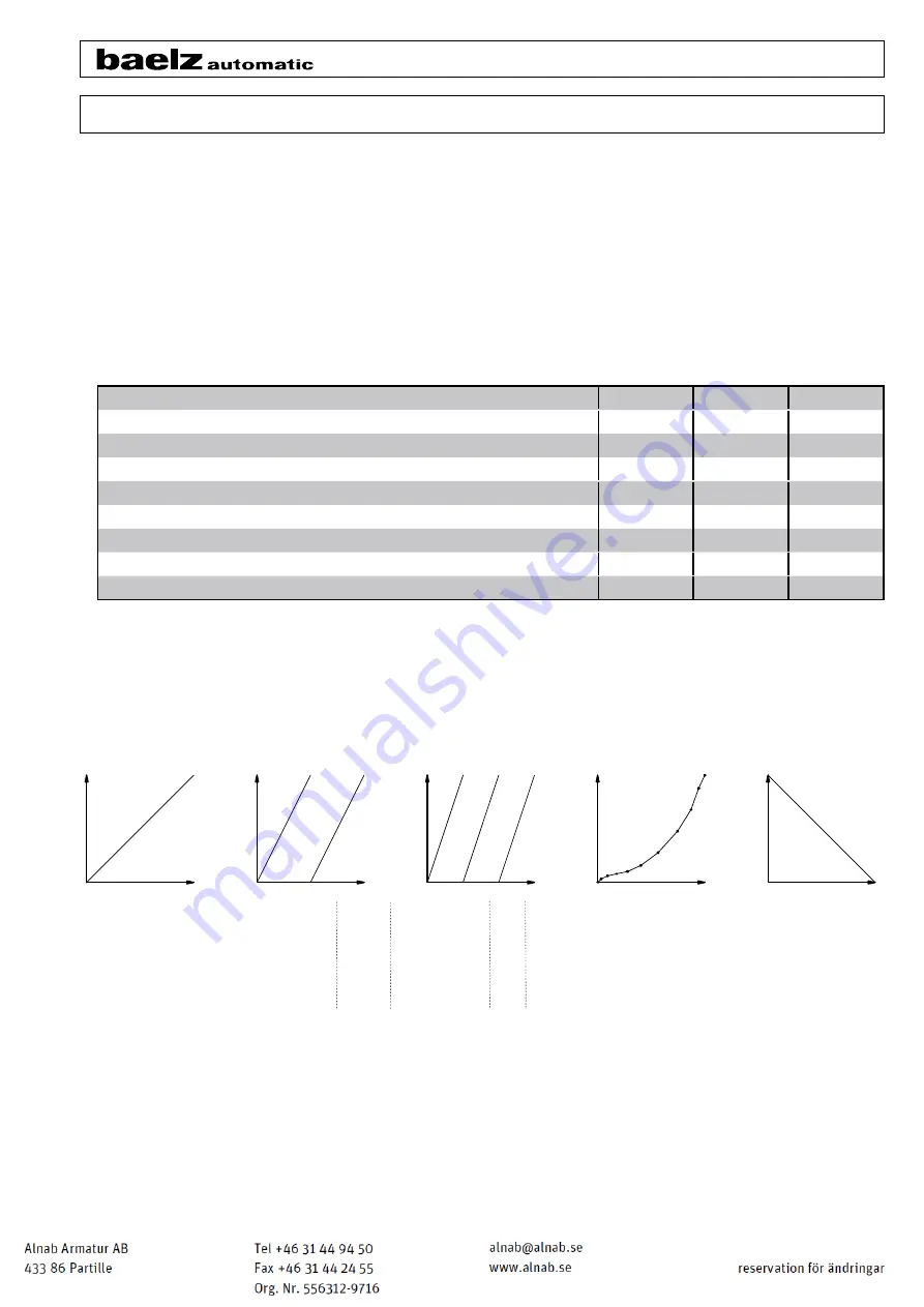
Fig. 7: Selection of function, input signal (AI2).
DIP switches 7, 8 and 9 operate together.
CLOSED
valvel 2, of
fset 50% [0 1 0]*
valve 1, of
fset 0% [1 0 0]*
valve 1, of
fset 0% [1 1 0]*
valve 2, of
fset 33.3% [0 0 1]*
valve 1, of
fset 66.6% [1 0 1]*
input signal
Valve position
OPEN
CLOSED
0%
100%
50%
33,3%
66,6,%
100%
0%
100%
0%
CLOSED
CLOSED
OPEN
OPEN
CLOSED
OPEN
OPEN
0%
100%
0%
100%
split range
split 50%
linear
split range
split 33%
11-point
characteristic
inverse linear
Fig. 8: Graphical illustration of selection of functions by DIP switches 7, 8, und 9
[0 0 0]
[0 1 1]*
[1 1 1]*
* [0 1 0], for example, means DIP 7 = 0, DIP 8 = 1, DIP 9 = 0 → split range mode, split 50%, offset 50%.


